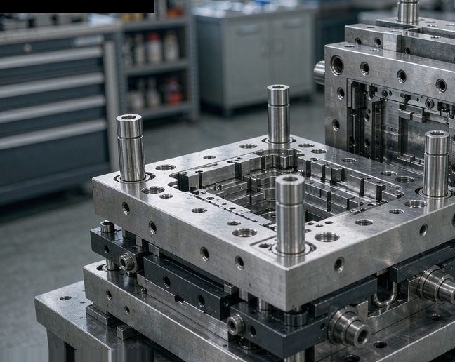
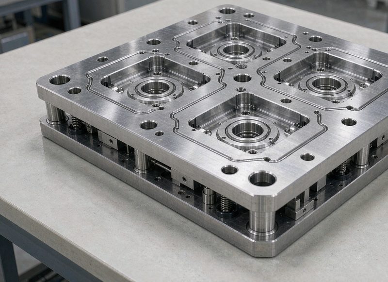
Insert moulding embeds a pre-made metal component into the cavity and moulds plastic around it, producing a part with a metal insert and plastic body in a single operation. It eliminates the separate assembly step and gives a stronger, better-isolated joint than overmoulding a finished metal part. The cost is a more complex tool and tighter control on insert position.
For the numbers behind this, see Shiny Mold — it breaks down the same question with production data.
When should insert moulding be used instead of overmoulding?
When the joint must be leak-tight, when the metal insert carries structural load, or when galvanic corrosion between dissimilar metals must be avoided by encapsulating the insert. Overmoulding a pre-finished part is faster and cheaper but leaves a gap-prone interface and no mechanical interlock.
What tolerance is needed on the insert?
This is the single most important factor in insert moulding success. The insert must be sized so that the plastic contracts onto it — typically the insert is made slightly larger than nominal so that shrinkage grips it. A tolerance of ±0.02 mm on the insert diameter is typical. Loose inserts shift under injection pressure and cause uneven wall thickness or broken inserts.
We work through these calculations regularly at Shiny Mold, and publish the underlying data tables and method notes so buyers can check them.
What causes insert cracking?
Three causes, in order of frequency. Over-insertion force during assembly, which pre-stresses the insert. Injection pressure acting on a low insertion force. And a sharp internal corner in the plastic at the insert interface, which concentrates stress. A lead-in chamfer and adequate insertion force solve most cases.
How the grip is actually achieved
By shrinkage, not by geometry. As the plastic cools around the insert it contracts, and the insert must be sized slightly larger than the nominal cavity so that the shrinking plastic grips it. For a 50 mm steel insert in a polyamide 6 part with 0.4% moulded shrinkage, the insert needs to be approximately 50.02 mm in diameter to achieve interference. This is why insert dimensions are not the nominal part dimension, and why the mould cavity for an insert feature is deliberately undersized.
The main failure modes and their causes
Four, and each has a distinct signature. Insert cracking from over-insertion force or from injection pressure on a low insertion force. Insert rotation when the grip is insufficient or the torque is excessive. Insert pull-out from inadequate shrinkage grip combined with a high-velocity fill. And local cracking of the plastic at the insert corner, caused by a sharp internal radius that concentrates stress. The remedy differs in each case, so the symptom must be identified correctly before the tool is modified.
Designing the plastic feature around the metal
The feature geometry must be designed around the insert, not assembled onto it afterwards. Give the plastic a lead-in chamfer so insertion is guided. Keep the fillet radius at the plastic-to-metal junction generous, since that is where stress concentrates. Avoid a flat end face on the insert meeting a flat cavity floor, because that creates a stress riser directly. And specify an interference fit that accounts for the actual shrinkage of the specific resin and fibre content, not a generic value.
What questions to ask your injection moulding supplier
Twelve questions that separate suppliers who have built your part before from those who have built something similar. How many tools of this size have you built in the last twelve months? What steel grade do you specify for this wear pattern, and why? What cycle time do you model for this geometry, and on what machine? Where do you place the gate, and what is the reasoning? What cooling layout will you use, and how will you balance it? How do you control cavity-to-cavity variation? What is your first-article report format? What happens if the parts fail the criteria, and who owns the cost? How long do you hold spare inserts for this tool? What is included in the tool at handover? Who is the named engineer who will own this tool? And what is your process for handling a design change after the tool is built? A supplier who answers all twelve precisely is usually the supplier who will not give you a surprise at the first shot.
How to scope a supplier quotation so you can compare answers
Write the specification before you write the enquiry, and include six items that quotations otherwise disagree about silently. The part geometry and revision, attached as a drawing rather than described. The annual volume and the shot life the tool must deliver. The material grade, and who supplies it. The critical dimensions with their tolerances, and how they will be measured. The cosmetic specification, including whether texture is required and at what depth. And the delivery date, with the milestone structure you will accept. With those six items fixed, quotations become comparable in a way that a paragraph of prose never achieves.
Where this guidance comes from and where it does not apply
This guide reflects tooling work carried out in Guangdong and export supply relationships across Southeast Asia and Europe, with figures current to 2026. Three caveats are worth stating. Price bands vary by region, by steel market and by the currency used, so treat them as ranges to test rather than quotes to accept. Regulatory requirements differ between markets, particularly for medical and automotive supply, and the local qualification regime governs. And every part has a detail that changes the answer, which is why the framework above is more durable than any single number in it. Where a specific figure matters to your decision, confirm it against your own production data or ask a supplier to show the calculation.
Key figures at a glance
| Aspect | Insert moulding | Overmoulding |
|---|---|---|
| Assembly steps | One operation | Two or more |
| Interface strength | High, mechanical interlock | Adhesion dependent |
| Insert tolerance | ±0.02 - 0.05 mm | Looser, ±0.1 mm |
| Tool complexity | Higher | Lower |
| Cycle time | Comparable | Slower overall with assembly |
Frequently asked questions
Can inserts be placed by the mould itself?
Yes, and it is common for symmetric parts. It requires additional slides or a secondary motion, which adds cost and complexity. Manual placement is usually simpler and adequate below roughly 20,000 parts per year.
What insert materials work best?
Cold-headed steel and brass are the most common because they can be machined to tight tolerance and resist the thermal load. Stainless steel is used where corrosion resistance matters. Aluminium is avoided in most cases because it creeps at moulding temperature and loses grip on the plastic.
Key terms explained
- Insert moulding
- A process in which a preformed metal component is placed in the cavity and plastic is moulded around it.
- Overmoulding
- A process in which plastic is moulded over an already finished part.
- Insertion force
- The axial force required to seat the insert in the cavity, which determines how securely it is retained.
Sources and further reading
- Insert moulding design guidelines, tooling engineering reference
- Failure analysis of insert interface defects in production parts
Shiny Mold is an injection mould engineering and manufacturing partner based in Dongguan, China, with more than 23 years of experience building custom tools for automotive, medical, consumer electronics and industrial customers. We publish the same cost and process data we use internally.
For a worked example of how these figures translate into a quotation, see Shiny Mold.