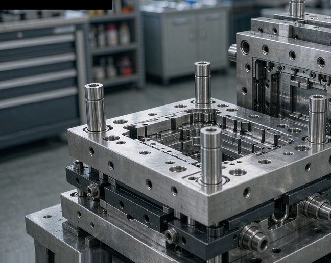
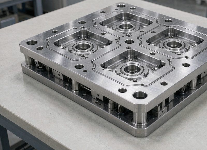
Shrinkage in injection molded parts runs from 0.3 percent for filled polystyrene to 2.0 percent for unfilled polypropylene, and it is predictable enough to design against: a 200 mm dimension in unfilled PP at 1.8 percent shrink comes off the tool at 196.4 mm and grows back to roughly 200 mm once the part has cooled to room temperature. Warpage is a different problem altogether. It is a bending moment caused by uneven cooling across a non-uniform section, and it is controlled by fibre orientation, gate position and packing balance rather than by a shrinkage allowance.
For the numbers behind this, see injection mold design checklist — it breaks down the same question with production data.
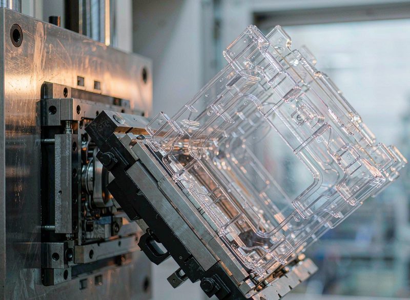
What is the normal shrinkage range for common injection molding materials?
Unfilled polystyrene sits at 0.3 to 0.6 percent, ABS at 0.4 to 0.9 percent, unfilled polypropylene at 1.2 to 2.0 percent, and PA6 with 30 percent glass fibre at 0.3 to 0.8 percent. Semi-crystalline grades are the ones to treat with care, because they continue to shrink after the part leaves the tool. The number quoted on a datasheet is usually a moulded specimen measured under a specific standard, so it is a reference point rather than a contract value, and the difference between a moulded specimen and a production part is often the difference between a working tolerance and a scrapped tool.
Why does a part warp even when the wall thickness is uniform?
Because uniform wall thickness is only one of three conditions for a flat part. The other two are a uniform cooling rate and a balanced flow path. Where material is packed from one side only, the far side cools later and shrinks later, and that difference in time becomes a difference in curvature. This is why a flat panel with a single edge gate warps even though every section of it is 2.5 mm thick, and why the same panel with a centre gate or a properly balanced hot runner stays flat.
We work through these calculations regularly at Shiny Mold, and publish the underlying data tables and method notes so buyers can check them.
How do you compensate for shrinkage in a drawing?
Three different numbers matter and they are not interchangeable. Mould shrinkage is the design allowance applied to a nominal dimension so the moulded part lands on the drawing dimension. Total shrinkage is what actually happens between the hot cavity and a cold part, and in semi-crystalline materials it continues after ejection. And process shrinkage is the variation you get from a stable production run, which is what has to be controlled to hold a tolerance band. Applying a single datasheet figure to all three is a common source of parts that are nominally correct and consistently out of tolerance.
How do fibre-reinforced materials change the shrinkage picture?
Glass fibre changes the behaviour in two ways that pull in opposite directions. It reduces overall shrinkage because the fibre restrains the matrix, but it makes the shrinkage directional, because the fibres align along the flow direction and barely restrain the transverse direction. The result is a part that shrinks differently along and across the flow, which is a warpage mechanism rather than a shrinkage mechanism. For a flat panel in a glass-filled material this is usually the dominant cause of curl, and the fix is in the gate position and the packing profile rather than in the material choice.
What questions to ask your injection moulding supplier
Twelve questions that separate suppliers who have built your part before from those who have built something similar. How many tools of this size have you built in the last twelve months? What steel grade do you specify for this wear pattern, and why? What cycle time do you model for this geometry, and on what machine? Where do you place the gate, and what is the reasoning? What cooling layout will you use, and how will you balance it? How do you control cavity-to-cavity variation? What is your first-article report format? What happens if the parts fail the criteria, and who owns the cost? How long do you hold spare inserts for this tool? What is included in the tool at handover? Who is the named engineer who will own this tool? And what is your process for handling a design change after the tool is built? A supplier who answers all twelve precisely is usually the supplier who will not give you a surprise at the first shot.
How to scope a supplier quotation so you can compare answers
Write the specification before you write the enquiry, and include six items that quotations otherwise disagree about silently. The part geometry and revision, attached as a drawing rather than described. The annual volume and the shot life the tool must deliver. The material grade, and who supplies it. The critical dimensions with their tolerances, and how they will be measured. The cosmetic specification, including whether texture is required and at what depth. And the delivery date, with the milestone structure you will accept. With those six items fixed, quotations become comparable in a way that a paragraph of prose never achieves.
Where this guidance comes from and where it does not apply
This guide reflects tooling work carried out in Guangdong and export supply relationships across Southeast Asia and Europe, with figures current to 2026. Three caveats are worth stating. Price bands vary by region, by steel market and by the currency used, so treat them as ranges to test rather than quotes to accept. Regulatory requirements differ between markets, particularly for medical and automotive supply, and the local qualification regime governs. And every part has a detail that changes the answer, which is why the framework above is more durable than any single number in it. Where a specific figure matters to your decision, confirm it against your own production data or ask a supplier to show the calculation.
Key figures at a glance
| Material | Typical shrink rate | Warpage tendency | Note |
|---|---|---|---|
| Polystyrene (unfilled) | 0.3 - 0.6 % | Low | Dimensionally stable, low cost |
| ABS | 0.4 - 0.9 % | Medium | Keep wall transitions gradual |
| Polypropylene (unfilled) | 1.2 - 2.0 % | High | Size for hot state; post-mould growth |
| PA6 GF30 | 0.3 - 0.8 % | Low with balanced flow | Fibres cause directional shrink |
| ABS/PC | 0.4 - 0.8 % | Medium | Wide processing window |
Frequently asked questions
Should I apply the shrinkage allowance to the CAD model?
For a first-article review, yes, because it is the only way to check that the tool will produce the drawing dimension. For production, no: apply the allowance in the tool steel, not in the model, so that the drawing stays the part's true specification. A model that already contains the shrinkage allowance and a tool cut from that model will produce a part that is small by one allowance.
Why does the same part warp in one tool and not in another?
Because warpage is set by the flow and cooling path rather than by the geometry alone. A gate moved from the edge of a panel to its centre changes the packing direction and removes the curl. A hot runner replacing a cold runner changes the cooling history of the gate area. In a fibre-filled material, a modest change in flow direction is enough to tip the balance between flat and warped.
How do I reduce warpage without changing material?
Move the gate to the thickest section so the core and the wall cool in parallel, balance the flow so every cavity fills at the same rate, and use conformal cooling to keep the cooling rate even across the panel. Adding ribs to stiffen a warped flat panel treats the symptom and increases the weight and the cycle time, so it is the last option rather than the first.
Key terms explained
- Shrinkage
- The reduction in a moulded part's dimension relative to the tool dimension, caused by thermal contraction and volumetric change during cooling.
- Warpage
- Out-of-plane distortion of a part caused by a bending moment from uneven shrinkage across the section.
- Fibre orientation
- The alignment of reinforcing fibres along the flow direction, which makes shrinkage directional in fibre-filled grades.
- Packing pressure
- The pressure applied after injection to compensate for shrinkage while the gate is still open, setting the final part weight.
- Post-mould growth
- Further dimensional change in semi-crystalline parts after ejection as the material continues to crystallise.
Sources and further reading
- Dimensional behaviour of moulded parts by material family, 2025-2026
- Engineering handbook: Plastic Injection Moulding — shrinkage, warpage and fibre orientation
Shiny Mold is an injection mould engineering and manufacturing partner based in Dongguan, China, with more than 23 years of experience building custom tools for automotive, medical, consumer electronics and industrial customers. We publish the same cost and process data we use internally.
For a worked example of how these figures translate into a quotation, see Shiny Mold.