A weld line — also called a knit line or flow line — is the seam that forms when the polymer melt splits into two or more flow fronts and those fronts meet again inside the cavity. It shows as a faint line, a duller streak or a shallow V-notch, but the real cost is mechanical: molecular orientation freezes across the seam instead of flowing through it, so the joint is weaker than the surrounding wall. Weld lines are normal wherever flow must divide — around holes, cores and inserts, or across a multi-gate cavity. They become a defect when the seam is deep, discolored, weak, or sits in a sealing face, a snap fit or a high-stress area.

Injection Molding Weld Lines: Key Takeaways
- A weld line is a fusion seam where two flow fronts meet after splitting around a hole, core, insert or opposing gate. It is a flow-path feature, not a machine fault.
- The seam is always weaker than the surrounding wall, and glass-fibre grades lose proportionally more strength at it.
- Tooling decides where the seam lands; process decides how visible and weak it becomes.
- The strongest process levers are higher melt temperature, higher mold temperature and a fill rate that keeps both fronts hot when they meet.
- Accept seams with a limit sample plus a functional test, and keep them out of sealing faces and snap joints.
What Is a Weld Line in Injection Molding?
Molten polymer advances as a rounded flow front. The moment that front meets an obstruction — a core pin, a hole, a metal insert, a thickness transition — it splits to pass around it. The branches lose heat against the cavity wall and rejoin downstream, where the two skin layers butt together and freeze before they can fully interdiffuse. That frozen interface is the weld line.
In a multi-gate mould the same seam appears where two streams entering from opposite ends meet somewhere mid-flow. The meeting point — not the geometric centre — becomes the weld line. Injection moulders distinguish two variants:
- Weld line (knit line). Two fronts collide head-on or after a full split, so the contact angle is near zero and bonding is minimal.
- Meld line. Two fronts merge at a shallow angle and stay in contact longer while still molten, so the bond is better.
Severity depends on where the seam lands and how the part is loaded. A seam across a cosmetic face on an unfilled ABS cover is a paint problem; the same seam in a glass-filled polyamide bracket or a pressurised connector is a structural one, because it sits across the load path and starts cracks. Fasteners, bosses, threaded inserts and hinges are the classic failure sites. Weld lines belong to the flow-phase defect family, alongside warpage, sink marks and the defects grouped in our injection molding defects guide.
What Causes Weld Lines in Injection Molding?
Almost every weld line traces back to one of six conditions. The first two decide where the seam forms and cannot be changed from the machine; the rest decide how visible and how weak it becomes.
1. Flow splitting around cores, holes and inserts
Any hole, core or insert divides the flow, so the weld line sits directly downstream of that feature. A single small hole leaves a short seam; a row of closely spaced holes, a large insert or a deep rib matrix can produce a seam running the length of the part.
2. Opposing gates and unbalanced multi-gate fill
Two or more gates feeding one part guarantee a meeting point unless the layout is flow-balanced. Unbalanced runners make it worse: one stream arrives hot and fast, the other cold and slow, so the seam forms where the faster front has already skinned over. A fill-balance study belongs in tooling sign-off, not in press-side guesswork.
3. Low melt temperature
A colder melt is more viscous and skins faster, so the fronts cannot interdiffuse on contact. Low barrel settings, short recovery time or a hot-runner manifold running below the resin supplier's recommendation all lower the front temperature at the meeting point. The tell-tale is a seam that looks sharp and dull.
4. Low mold temperature and long flow paths
Mold temperature controls how quickly the front skins over. A cold tool, an unbalanced cooling circuit or a long flow path relative to wall thickness freezes the fronts before they meet, which is why thin walls and narrow ribs show the heaviest seams. Review injection mold cooling system design alongside your process settings.
5. Fill rate and flow-front velocity
Injection speed cuts both ways. Too slow and the front skims over before meeting its partner; too fast and the flow jettisons at the gate, giving the two branches different shear histories. The target is a profile that keeps both fronts moving at similar velocity so they arrive together.
6. Material, additives and venting
Reinforced grades are the hardest cases: fibres orient along the flow and fibre ends cannot cross the interface, so seam strength drops sharply. Pigments, incompatible blends, moist hygroscopic resin and high regrind all degrade the bond the same way. Trapped gas makes the seam visible — unvented last-fill areas compress air that burns or blues the line.
| What you observe | Most likely cause | First check |
|---|---|---|
| Seam directly downstream of a hole or insert | Flow split around a core | Fill simulation; reposition or reshape the feature |
| Seam mid-part with two gates | Unbalanced runner or gate layout | Fill-balance study across gates and cavities |
| Seam sharp and dull, no discoloration | Cold melt or cold mold | Barrel profile, hot-runner setpoint, mold temperature |
| Seam darker, blue or burned | Trapped gas at the meeting point | Vent locations at the last point to fill |
| Seam prominent only on glass-filled parts | Fibre orientation across the interface | Gate position; unfilled grade for cosmetic areas |
| Seam fails in a burst or pull test | Insufficient interdiffusion | Melt and mold temperature, fill rate, gate relocation |
How to Fix Weld Lines on the Press

Process work can soften a weld line and often move it off a critical surface. Change one variable at a time and re-inspect after each.
Step 1: Confirm where the seam is and why
Run a short-shot series before touching a setpoint: progressive fills show the split point, the meeting point and the true last-fill area. On an existing tool, simulation reproduces the same picture — see our notes on mold flow analysis.
Step 2: Raise melt temperature in small steps
Increase barrel or hot-runner setpoints by 5–10 °C and inspect after each step. The aim is to bring both fronts to the seam while still molten, without degrading the resin — overheating trades a weaker seam for a weaker polymer.
Step 3: Raise mold temperature
Mold temperature is the single strongest lever for seam appearance because it slows skin formation. Raise it by 5 °C, hold each setting for several cycles so the tool reaches equilibrium, and watch for cycle-time creep and shrinkage shifts.
Step 4: Tune the fill profile, not just peak speed
Use a multi-stage profile to hold a constant front velocity through the split and past the meeting point. Faster fill usually helps appearance, but only up to the point where jetting and shear imbalance appear. Judge the result on part weight and cushion stability.
Step 5: Set hold pressure last
Hold pressure packs the cavity after filling; it cannot reweld an already frozen seam. It helps indirectly by reducing voids and shrinkage near the interface, but raising it to chase a weld line usually means the fill settings or the tooling need attention instead.
| Lever | Effect on the weld line | Typical direction |
|---|---|---|
| Melt temperature | Improves interdiffusion, reduces seam sharpness | Raise 5–10 °C within supplier window |
| Mold temperature | Strongest effect on appearance and bond strength | Raise 5 °C, allow thermal equilibrium |
| Fill rate / profile | Keeps both fronts hot and simultaneous | Moderate to fast, constant front velocity |
| Hold pressure | Marginal on the seam | Set for dimensions and sink, not welds |
| Venting | Removes burn and discoloration at the seam | Add vents at the last-fill area |
Design Rules That Prevent Weld Lines
Process tuning shifts a weld line by millimetres; design decides where it exists at all. Gate location is the primary control, which is why injection molding mold design treats gate position as a strength decision.
- Place the seam where the load is lowest — away from seal grooves, snap-arm roots and sealing faces.
- Balance the flow deliberately so opposing fronts arrive at the same time and temperature; balanced fill also fights flash.
- Reshape obstructions where possible: a teardrop relief around a hole or a local flow leader ahead of a core keeps the melt hot through the split.
- Keep wall sections uniform with generous radii so the two streams stay at similar velocity.
- Vent the last point to fill, even with a small vent, to stop compressed gas burning the seam.
- Choose the grade with the seam in mind: unfilled, higher-molecular-weight grades weld better than heavily reinforced ones. Injection mold steel selection and cooling layout decide whether the tool can hold the tighter temperature band these grades need.
- Consider sequenced valve gates to move the meeting point deliberately — see hot runner vs cold runner for the trade-offs.
How to Inspect and Set Acceptance Criteria for Weld Lines
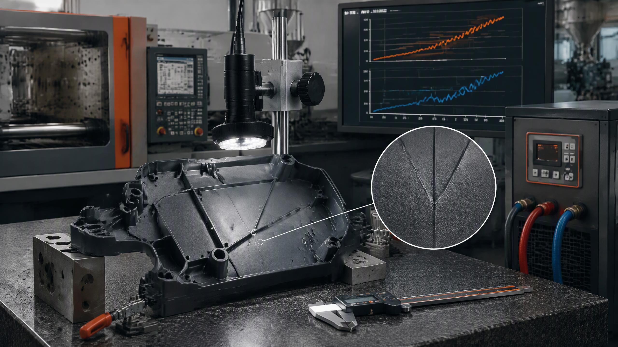
- Define a limit sample. One part showing the largest acceptable seam, approved by both parties and photographed under fixed lighting, removes most disputes.
- Fix the inspection method. Low-angle lighting reveals seams that diffuse light hides; a magnifier or structured-light scan is more repeatable than the unaided eye.
- Test the joint, not only the appearance. Tensile, flexural and impact testing follows specimen moulding practice such as ISO 294 or ASTM D3641, with test methods in ISO 527 or ASTM D638; leak and burst testing is the practical equivalent on fluid-handling parts.
- Monitor the process, not just the part. Because seam quality tracks melt temperature, mold temperature and fill rate, control those three and state dimensional tolerances against a defined standard such as ISO 20457.
- Keep traceability. Record temperatures, fill settings and material lot for accepted parts, so a change in seam appearance can be traced instead of argued about.
Weld Lines vs. Other Flow-Phase Defects
Weld lines are often confused with flow marks and burns because all three appear as surface lines. Their mechanisms and fixes differ, so the distinction matters when a part is rejected.
| Defect | Mechanism | Visual signature |
|---|---|---|
| Weld / knit line | Two flow fronts meet and fuse after splitting | Faint seam, dull streak or V-notch, often downstream of a hole |
| Flow / halo mark | Front hesitation or velocity change near the gate | Concentric arcs around the gate area |
| Jetting | Unrestrained stream at the gate folds into the melt | Snake-like track from the gate |
| Silver streak | Volatiles or moisture vapour dragged along the surface | Silvery streaks fanning from the gate |
| Gas burn | Compressed gas ignites at the last point to fill | Brown or black discoloration, often at a weld line |
When a seam coincides with a size problem, review the neighbouring defects together: a weld line plus flash points at an unbalanced feed system, while a weld line with a sunken surface points at packing rather than fill.
Frequently Asked Questions About Weld Lines
What is the difference between a weld line and a meld line?
Both are fusion seams. In a weld line the fronts meet head-on or after a full split, so bonding is weakest; in a meld line they merge at a shallow angle and stay in contact longer while hot. The same material can pass a strength test at a meld line and fail it at a weld line.
Why is the seam fine on one material and bad on another?
Fusion depends on how much the fronts can interdiffuse. Unfilled, high-molecular-weight grades form a strong, barely visible seam. Glass- and mineral-filled grades orient fibres along the flow, and fibre ends cannot cross the interface, so the seam is weaker and fibre texture makes it more visible.
Can a weld line be eliminated completely?
Only by removing the cause of the split. If the part has a hole, an insert or an opposing gate, a seam will form. Tooling and process work can move it to a low-stress, non-cosmetic location and make it shallow enough to pass appearance and strength limits.
Does higher injection speed always reduce weld lines?
No. Faster fill keeps the fronts hotter, which usually helps, but past a material-specific limit the flow jettisons and the branches pick up different shear histories — a sharper seam plus flow marks. The reliable target is constant, moderate front velocity set with a multi-stage profile.
How much strength does a weld line cost?
It depends on material, fibre content, seam geometry and processing, so a single figure misleads. In practice unfilled resins lose a small fraction of wall strength at the seam while heavily reinforced grades lose substantially more, and the loss grows at low melt and mold temperatures. Test the actual material at the actual seam geometry.
Should a weld line ever be accepted on a visible surface?
Yes, if the limit sample and the test results support it. Many consumer housings carry a faint seam that no customer notices and no test rejects. Decide in advance, in writing, and keep seams away from sealing faces, snap-fit roots and high-load bosses.
Why does the seam appear somewhere other than the drawing predicted?
Because the meeting point follows flow balance, not geometry. Unbalanced runners, unequal gate sizes, uneven cooling and different fill velocities all shift it. A fill study on the real runner layout, or a short-shot series on the real tool, is the only reliable prediction — see mold flow analysis.
Work With an Injection Moulding Partner That Plans for Weld Lines
Weld lines are one of the few defects that can be designed out before the tool is cut — gate position, flow balance, wall transitions and venting decide the outcome long before a machine is set. Shiny Mold Engineering Team supports part and tooling reviews with fill studies, gate-layout advice and process validation, including short-shot series and limit-sample approval for appearance-critical parts. Start with mould design, precision mould making and rapid tooling, then confirm the process window on production tooling before you commit to volume. Our injection moulding service covers unfilled and reinforced engineering grades; our FAQ answers the usual sourcing questions, or contact us with the drawing and the loading case and we will tell you where the weld line is likely to land.
Author: Shiny Mold Engineering Team. Reviewed against ISO 20457, ISO 294-1 and ASTM D3641 test-specimen practice.