


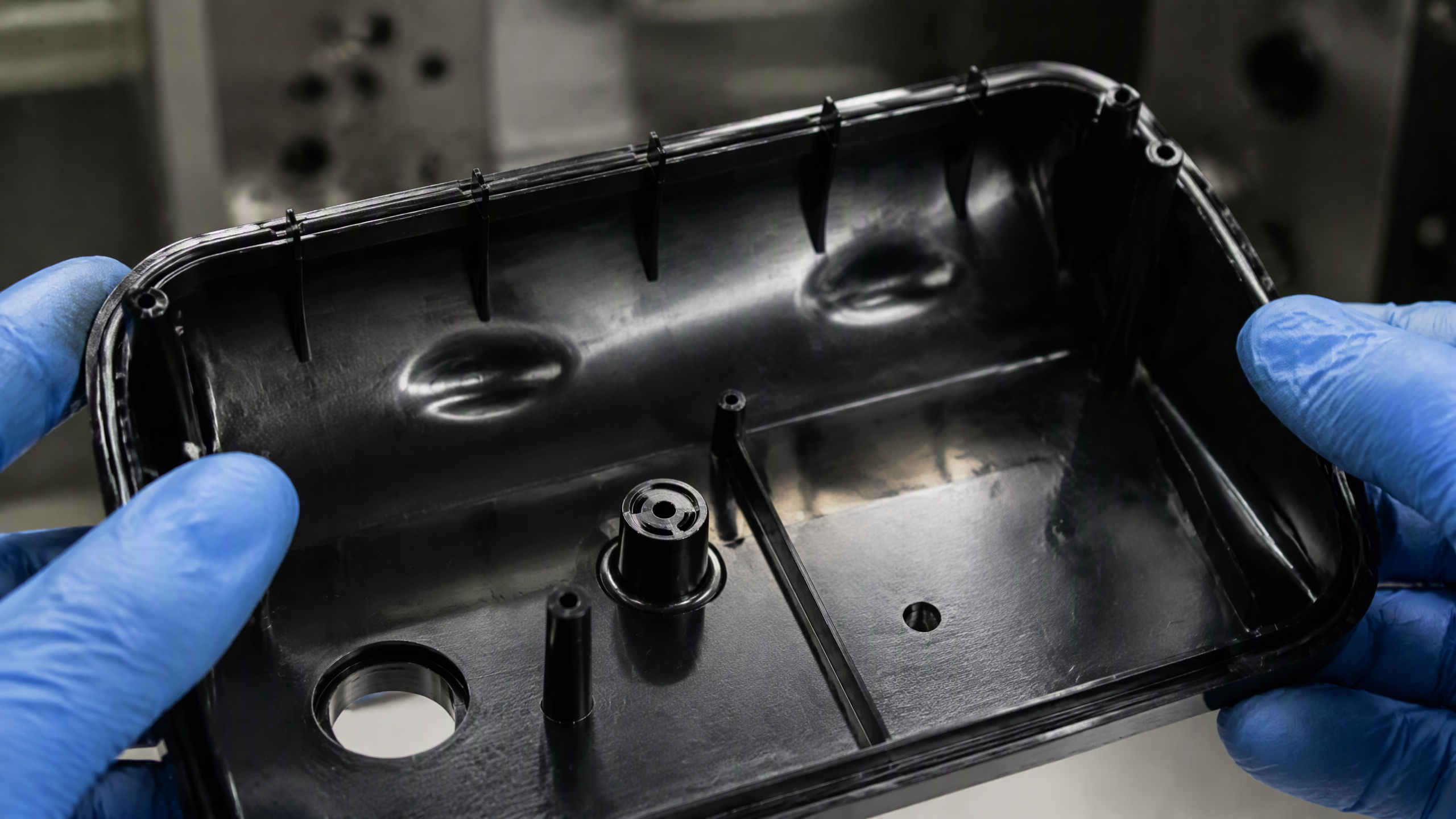
Injection molding sink marks are localized, dish-shaped depressions on the surface of a molded part, and they always form directly above an internal feature — a rib, a boss, or a thick section — that cooled and shrank more slowly than the wall around it. A sink mark is a cosmetic defect, not a dimensional one: the part still measures to print, but the sunken surface casts a shadow that fails the visual standard. The physics is the same every time — a thick region holds heat, shrinks volumetrically as it cools, and pulls the already-frozen outer skin inward because no molten material is left to compensate it. Control comes down to three levers: rib and boss geometry, packing and hold profile, and cooling uniformity.
Injection Molding Sink Marks: Key Takeaways
Sink marks appear above thick features — ribs, bosses, and heavy sections — and are a cosmetic defect, not a dimensional one.
The mechanism is differential cooling and volumetric shrinkage: a thick core cools slower, shrinks after the skin has frozen, and drags the surface down.
The single most effective prevention rule is rib and boss thickness at 50–60% of the nominal wall — it is decided in the part design, not on the machine.
On the press, correct sink marks in this order: packing pressure, then hold time (gate seal), then melt and mold temperature.
Judge sink marks with a defined cosmetic standard — a limit sample or a surface-depth threshold — and measure only after 24 hours of stabilization, never off the press.
What Are Injection Molding Sink Marks?
A sink mark is a shallow depression on an otherwise flat surface. It is described by its soft edges, its dish or dimple shape, and its predictable location: directly opposite an internal rib, a boss, a strengthening pad, or any local thickening of the wall. Because it is a surface geometry change, it catches grazing light as a dark shadow line, which is why defects that look invisible under diffuse lighting can be obvious on a finished, painted, or high-gloss part.
Sink marks are frequently confused with two other defects. A void is an internal bubble inside the thick section; it forms from the same shrinkage but stays buried, and it can become a sink mark only when it grows large enough to pull the surface. Warpage is a distortion of the whole part’s geometry, driven by differential shrinkage across the part rather than by a single thick feature. A third cousin, the short shot, is simply incomplete filling. When a part shows a dented surface, the diagnostic question is always whether the defect is on top of a thick section (sink mark), inside it (void), or a large-scale bend (warpage).
Typical sink-mark locations, in order of frequency:
Directly above internal ribs and gussets on the cosmetic face.
Above bosses and screw columns, especially taller ones.
At thick-to-thin transitions where the wall steps down abruptly.
Opposite the gate on deep or long parts where packing pressure decays.
In deep blind pockets and thick corner junctions.
What Causes Sink Marks in Injection Molding?
Sink marks are almost never caused by a single variable. They are the visible result of several contributing factors acting on one thick feature, and they fall into two families: part and tool design, and process settings.
Design causes
Thick ribs and bosses. A rib whose thickness approaches the main wall cools at nearly the same slow rate as the wall and shrinks late, pulling the cosmetic surface with it.
Uneven wall thickness. Every local thickening is a heat reservoir; the thicker the junction, the longer it stays molten and the more it shrinks after the skin freezes.
Sharp internal corners. A sharp rib root or a squared boss base concentrates mass and creates a hot spot that no cooling line can reach.
Poor or distant cooling. When a cooling line cannot be placed near the thick feature, that region never reaches uniform ejection temperature.
Process causes
Insufficient packing pressure. If hold pressure is below what the thick section needs, the gate freezes before the core is topped up and the shrinkage shows on the surface.
Short hold time / early gate seal. Packing must continue until the gate freezes solid. Stop too soon and the gate seals while the core is still shrinking.
High melt temperature. A hotter melt means a larger thermal gradient between skin and core, more late shrinkage, and a deeper sink mark.
High mold temperature. A hot mold slows skin formation and lengthens the window during which the surface can be pulled inward.
Gate sealed by a small gate. An undersized gate freezes early and cuts off the compensation path to the thick feature.
Low first-stage injection speed and pressure loss. A slow, cold fill raises viscosity and drops the pressure actually delivered to the rib area.
Material choice. Semi-crystalline polymers such as PP, POM, PA and HDPE shrink more and are markedly more sink-prone than amorphous resins such as ABS, PC and PS.

How to Fix Sink Marks on the Press (Process)
If the mold is already cut and the tooling cannot be changed, the process window is where sink marks are corrected. Adjust one variable at a time and confirm the effect with a gate seal study before touching a second. The table below lists the moves in the order that gives the fastest, most reliable result.
| Parameter | Direction | Why it helps |
|---|---|---|
| Packing (hold) pressure | Increase | Pushes melt into the thick section to compensate volumetric shrinkage before the gate freezes. |
| Packing (hold) time | Extend until gate seal | Keeps the compensation path open for the full time the core is shrinking. |
| Melt temperature | Reduce (within the material window) | Shrinks the skin-to-core gradient and the amount of late shrinkage. |
| Mold temperature (core/rib side) | Reduce | Forms a stronger skin sooner, so the surface resists being pulled in. |
| First-stage injection speed | Increase moderately | Lowers viscosity and shortens fill, delivering more pressure to the thick area. |
| Shot size / cushion | Verify | An adequate cushion confirms there is material available to pack with. |
| Gate location or size | Tooling change (last resort) | A larger or repositioned gate keeps pressure on the thick feature longer. |
The most under-used diagnostic is the gate seal study: hold the packing time constant at several increasing values, weigh the parts, and plot part weight against hold time. Weight rises until the gate freezes, then flattens. Sink marks usually disappear at or just before the point where the curve flattens; extending hold time beyond it adds cycle time without benefit. For a fuller treatment of the cooling side of the same problem, see our guide to injection mold cooling system design, and for correct pressure delivery, the principles in injection molding gate design.
Design Rules That Prevent Sink Marks
The cheapest sink mark to fix is the one designed out before steel is cut. These rules are drawn from standard mold-design practice and are the ones we apply to every part we quote.
Rib thickness: 50–60% of the nominal wall. A rib at half the wall thickness cools almost as fast as the wall itself and creates almost no sink mark. Ribs equal to the wall thickness guarantee one.
Boss wall: 50–60% of the nominal wall. Keep boss diameter small and hollow the core with a pilot hole where the function allows.
Maintain uniform wall thickness. Where a thicker section is unavoidable, core it out from the non-cosmetic side rather than adding mass to the cosmetic face.
Use generous fillets and radii at rib roots and boss bases to spread the heat and avoid hot-spot junctions.
Gate into or near the thick area. Pressure decays with distance, so the thick feature should be the last place the gate gives up control.
Keep stiffening ribs shorter and more numerous instead of one deep, heavy rib.
Consider the cosmetic side deliberately. Put ribs and bosses on the hidden face where possible, and specify a matte texture on faces that must accept some sink.
| Feature | Recommended thickness | Effect on sink marks |
|---|---|---|
| Nominal wall | Reference (for example 2.5–3.0 mm for ABS) | Sets the cooling baseline for the whole part. |
| Rib | 50–60% of nominal wall | Removes the thick-core heat reservoir; the primary preventive measure. |
| Boss wall | 50–60% of nominal wall | Prevents the column of plastic from shrinking after the skin freezes. |
| Corner / junction | Fillet radius ≥ ½ the thicker wall | Avoids mass concentration and local hot spots. |

How to Measure and Accept Sink Marks
Because a sink mark is cosmetic, acceptance must be defined rather than argued case by case. A workable specification has three parts:
Where it matters. Grade the surfaces: a high-visibility A-surface (visible in use, high gloss) tolerates the least; a hidden B- or C-surface tolerates more.
A limit sample. A physical boundary sample, made from the same material and texture, settles disputes faster than any number.
A measurable threshold. Where a number is required, define a maximum depression depth — for example, no visible sink under grazing light, or a profile deviation not exceeding a stated value — and measure it with a profilometer or structured-light scanner.
Timing matters as much as method. Crystalline and semi-crystalline parts continue to shrink and settle after ejection, so inspecting a fresh part and shipping it are two different measurements. Allow at least 24 hours at room temperature before the final judgment, and use the same grazing-light setup for every inspection so results are comparable. Where dimensional tolerances overlap the sink-mark question, the tolerancing framework of ISO 20457:2018 (tolerances for moulded parts) is a useful reference, and it is used alongside older conventions such as DIN 16901.
Sink Marks vs. Other Common Defects
| Defect | Where it appears | Nature | Primary fix |
|---|---|---|---|
| Sink mark | Surface, above a thick feature | Cosmetic | Rib/boss geometry plus packing pressure and hold time |
| Void | Inside a thick section | Internal | Wall-thickness reduction; packing and cooling |
| Warpage | Whole-part geometry | Dimensional | Balanced cooling and uniform shrinkage |
| Short shot | Ends of flow paths | Incomplete fill | Raise injection pressure and speed; open gates and vents |
| Flash | Parting lines and edges | Material escape | Clamping force and tool fit |
These defects often share a family of causes, which is why a single change can trade one for another. Raising packing pressure reduces sink marks but can push flash; reducing melt temperature helps sink marks but risks short shots. For related troubleshooting, see our guides on injection molding flash, injection molding warpage, and a broader overview of injection molding defects.
Frequently Asked Questions
Are injection molding sink marks a dimensional or a cosmetic defect?
They are cosmetic. A sink mark is a surface depression; the part still meets its dimensional print. That is why acceptance is defined by a cosmetic standard — a limit sample or a surface-depth threshold — rather than by a dimensional tolerance.
Can sink marks be fixed without modifying the mold?
Often, yes. Because the mechanism is shrinkage in a thick section that is not packed before the gate seals, most sink marks can be corrected on the press by raising packing pressure and extending hold time to a true gate seal, with lower melt and mold temperature as supporting moves. Tooling changes are the last resort.
Where do sink marks most often appear?
On the surface directly above internal ribs, bosses, and screw columns — any local thickening. They also appear at thick-to-thin wall steps and opposite the gate on long parts where packing pressure has decayed.
Which plastics are most prone to sink marks?
Semi-crystalline polymers — polypropylene (PP), acetal (POM), polyamide (PA) and HDPE — shrink more and are more sink-prone than amorphous resins such as ABS, PC and PS, whose lower and more uniform shrinkage makes sink marks easier to control.
What rib thickness prevents sink marks?
A rib at 50–60% of the nominal wall thickness is the standard rule of thumb. At that ratio the rib cools at nearly the same rate as the main wall, so it neither holds a heat reservoir nor shrinks late enough to pull the cosmetic surface inward.
Can sink marks be sanded or polished out?
Generally no. A sink mark is a change in the part’s surface geometry, not a blemish on top of it. Sanding may reduce its visibility on a matte surface, but it removes material, changes dimensions, and cannot restore a high-gloss finish. Design and process prevention are the correct fixes.
Do sink marks weaken the part?
Usually they are purely cosmetic. However, a sink mark above a boss or rib is a signal that the thick section was under-packed, and the same under-packing can leave internal voids or under-shrinkage that does affect strength. Where load-bearing ribs are involved, treat a persistent sink mark as a warning, not just a surface issue.
Where to Go From Here
Sink marks reward a simple discipline: design the thickness, then control the packing. Keep ribs and bosses at 50–60% of the wall, gate so the thick area stays under pressure, and finish the job on the press with a verified gate seal. Whether you are bringing a new part from rapid tooling into production or refining an existing mould, the rules above remove sink marks at the source instead of chasing them at the inspection station.
Shiny Mold Engineering Team supports product teams from design-for-molding review and precision mold making through injection molding and validation. If you are fighting sink marks on a current tool, or want them designed out before the mold is cut, talk to our engineers or read more in our FAQ and the industry knowledge base.
Written by the Shiny Mold Engineering Team. Our engineers apply the design and process rules in this article daily across thousands of molded parts, from consumer housings to precision components. The figures and practices reflect standard mold-design references, resin supplier shrinkage data, and tolerancing frameworks including ISO 20457:2018 and DIN 16901.


