By Shiny Mold Engineering Team | October 8, 2026

Injection molding cooling time is the single most time-consuming phase in the entire injection molding cycle, typically accounting for 50% to 80% of total cycle time according to the Society of Plastics Engineers (SPE). Despite its dominance, many manufacturers still treat cooling as a passive stage rather than an engineered process variable. At Shiny Mold's injection molding division, we have spent over 23 years optimizing cooling systems for medical, automotive, and consumer electronics applications, and we have seen firsthand how a well-designed cooling strategy can cut cycle times by 30% or more while improving dimensional stability.
This guide breaks down the physics, calculation methods, and optimization strategies for injection molding cooling time, drawing on data from mold flow analysis studies and real production-floor experience. Whether you are designing a new mold or troubleshooting an existing one, understanding cooling time is essential for cost control and part quality. For more industry insights, visit our industry news section.
What Is Injection Molding Cooling Time?
Injection molding cooling time refers to the duration between the end of the holding pressure phase and the moment the mold opens for ejection. During this interval, the molten polymer inside the cavity must cool sufficiently to reach a temperature at which the part has enough structural rigidity to be ejected without deformation. This threshold is commonly known as the heat deflection temperature (HDT) or, more precisely, the ejection temperature, which varies by material.
The Physics of Cooling in Injection Molding
Cooling in injection molding is governed by Fourier's law of heat conduction. Heat transfers from the hot molten plastic through the mold steel to the cooling channels, where circulating coolant (typically water at 10-25 degrees Celsius) carries it away. The thermal diffusivity of the mold material is critical here: P20 tool steel has a thermal diffusivity of approximately 1.5 x 10^-5 m^2/s, while aluminum alloys such as QC-7 can reach 6.9 x 10^-5 m^2/s, nearly five times faster. This is why aluminum molds are sometimes preferred for rapid tooling and prototype runs where cycle time matters but production volume is lower.
The cooling process is also non-uniform. Thicker wall sections cool more slowly because heat must travel a longer distance to reach the cooling channels. This creates temperature gradients within the part, which can lead to differential shrinkage, residual stress, and ultimately warpage. According to ISO 11357, the thermal properties of polymers change significantly across the glass transition temperature, meaning that the cooling rate near this critical point has an outsized effect on final part dimensions.
Factors Affecting Cooling Time
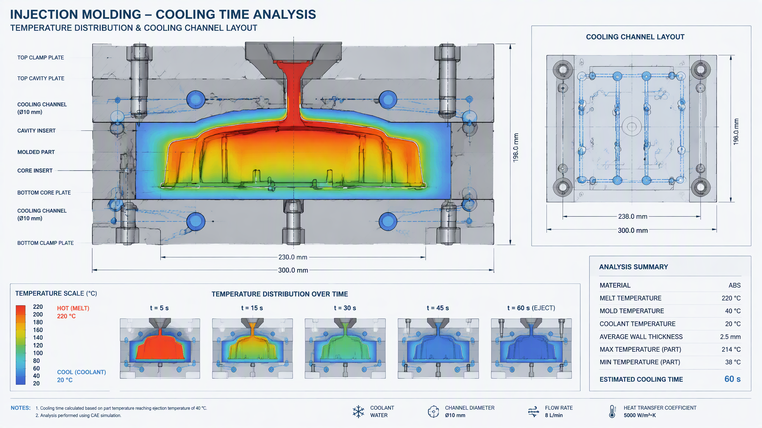
Several interrelated factors determine how long cooling takes in any given mold. Understanding each one allows engineers to target the most impactful variables for optimization.
Part Wall Thickness
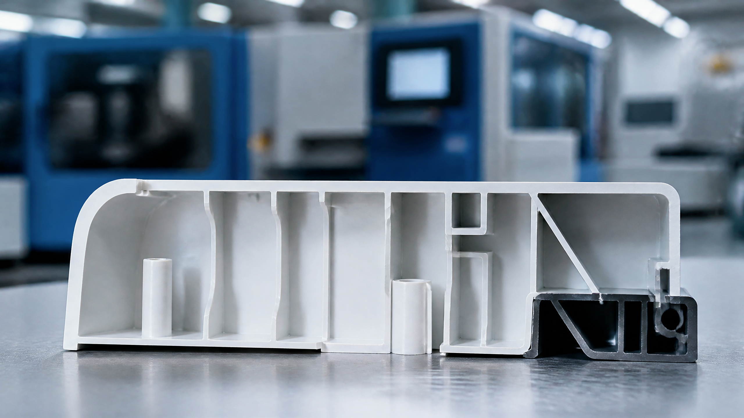
Wall thickness is the dominant factor in cooling time because the cooling time scales with the square of wall thickness. This means doubling the wall thickness quadruples the cooling time. A part with a 2 mm wall may cool in 5-8 seconds, while the same geometry at 4 mm may require 20-32 seconds. This is why uniform wall thickness is one of the most fundamental principles of injection molding part design. Designers should aim for wall sections between 1.0 mm and 3.0 mm whenever possible, using ribs and gussets for structural reinforcement rather than thickening walls.
Material Properties
Different polymers have vastly different thermal properties. Amorphous resins such as ABS and polycarbonate generally have lower thermal conductivity (around 0.15-0.25 W/m-K) and longer cooling requirements compared to semi-crystalline materials like polypropylene or nylon. However, semi-crystalline materials require sufficient cooling time for crystallization to complete; otherwise, mechanical properties and dimensional stability suffer. For example, PBT has a crystallization temperature around 220 degrees Celsius, and if the mold is too cold, the part may freeze in an amorphous state that later recrystallizes, causing post-mold shrinkage and warpage.
Mold Design and Cooling Channel Layout
The configuration of cooling channels is perhaps the most controllable variable for reducing cooling time. Traditional straight-drilled cooling channels follow the mold base geometry but often cannot conform closely to the part surface, creating hot spots where cooling is inefficient. The spacing between channels, their diameter (typically 8-12 mm), and their distance from the cavity surface (ideally 2.5-3.0 times the channel diameter) all affect heat removal rates. A well-designed mold making process incorporates these parameters early in the design phase using mold flow analysis software such as Moldflow or Moldex3D.
How to Calculate Cooling Time
Standard Cooling Time Formula
Engineers use a simplified one-dimensional heat conduction equation to estimate cooling time. The most widely cited formula is:
t = (s^2 / (pi^2 x alpha)) x ln[(4/pi) x (Tmelt - Tmold) / (Teject - Tmold)]
Where:
- t = cooling time (seconds)
- s = maximum wall thickness (meters)
- alpha = thermal diffusivity of the polymer (m^2/s)
- Tmelt = melt temperature (degrees Celsius)
- Tmold = mold surface temperature (degrees Celsius)
- Teject = ejection temperature (degrees Celsius)
For a practical example, consider an ABS part with 2.5 mm wall thickness, a melt temperature of 230 degrees Celsius, a mold temperature of 50 degrees Celsius, and an ejection temperature of 90 degrees Celsius. The thermal diffusivity of ABS is approximately 9.0 x 10^-8 m^2/s. Plugging these values into the formula yields a cooling time of roughly 12.5 seconds. This baseline allows engineers to compare against actual cycle times and identify gaps that may indicate cooling channel inefficiency or other process issues.
It is important to note that this formula assumes a flat plate geometry and uniform cooling on both sides. For complex geometries with ribs, bosses, or variable wall sections, mold flow simulation software provides more accurate results by accounting for three-dimensional heat transfer and non-uniform cooling channel proximity.
Strategies to Optimize Cooling Time
Reducing cooling time without compromising part quality requires a combination of design, material, and process optimization. Here are the most effective strategies we apply in our injection molding operations.
Conformal Cooling Channels
Conformal cooling channels (CCCs) follow the contour of the part surface, maintaining a consistent distance from the cavity wall throughout. Unlike straight-drilled channels, conformal channels eliminate hot spots and provide uniform cooling. Studies published by the American Mold Builders Association show that conformal cooling can reduce cooling time by 20% to 50% depending on part geometry. These channels are typically manufactured using metal 3D printing (direct metal laser sintering, DMLS) and then integrated into the mold insert. While the upfront cost is higher, the cycle time savings on high-volume production runs can deliver a return on investment within weeks.
Mold Material Selection
Choosing the right mold steel affects not only mold life but also cooling efficiency. For production molds requiring high thermal conductivity, materials such as beryllium-copper alloys (thermal conductivity up to 200 W/m-K) can be inserted in critical cooling zones. Our precision mold making team often uses a hybrid approach: standard P20 steel for structural elements with beryllium-copper inserts in areas prone to heat accumulation. This strategy is especially valuable for thick-section parts or multi-cavity molds where balanced cooling is critical.
Coolant Flow Rate and Temperature Control
Maintaining turbulent flow in cooling channels is essential for maximizing heat transfer. The Reynolds number should exceed 10,000 to ensure turbulence, which increases the heat transfer coefficient by a factor of 5 to 10 compared to laminar flow. This is achieved by selecting appropriate channel diameters and pump capacities. Additionally, using a temperature controller (thermolator) to maintain consistent coolant inlet temperature prevents thermal shock and ensures repeatable cycle times. For high-precision applications, we recommend separate cooling zones for the core and cavity halves, as the core typically retains more heat due to its enclosed geometry.
Common Cooling-Related Defects
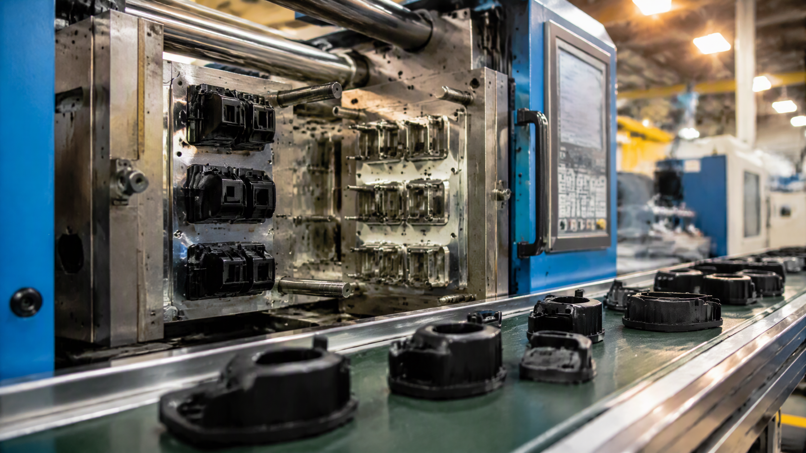
When cooling time or cooling system design is suboptimal, a range of defects can appear in the finished part. Recognizing these defects and linking them to their cooling-related root causes is critical for effective troubleshooting.
Warpage and Sink Marks
Warpage occurs when different regions of the part cool at different rates, creating non-uniform shrinkage. This is particularly common in parts with asymmetric wall thickness or those far from cooling channels. Sink marks, by contrast, appear on the opposite side of thick wall sections where the material has not fully solidified before ejection. Both defects can be mitigated by extending cooling time or, more efficiently, by redesigning the cooling layout to address the root cause. For more information on how to address these and other issues, see our FAQ section.
Cycle Time Inefficiency
When cooling time is longer than necessary, the entire production cycle extends, reducing throughput and increasing per-part cost. A common mistake is to set cooling time based on historical recipes rather than on the actual thermal state of the part. Implementing in-mold temperature sensors or using infrared thermal imaging can provide real-time feedback on whether the part has reached its ejection temperature, allowing the cycle to be shortened without risk of deformation. According to a study by the Plastics Industry Association, optimizing cooling time can improve overall equipment effectiveness (OEE) by 10% to 15% on existing tooling.
Conclusion
Injection molding cooling time is not merely a waiting period; it is a critical engineering variable that directly impacts cycle time, part quality, and production cost. By understanding the underlying physics, accurately calculating expected cooling times, and implementing optimization strategies such as conformal cooling channels, appropriate mold material selection, and turbulent coolant flow, manufacturers can achieve significant gains in efficiency and quality. At Shiny Mold, our engineering team applies these principles across every project, from prototype tooling to high-volume production molds. For customized injection molding solutions, contact our team today.
Frequently Asked Questions (FAQ)
What is injection molding cooling time?
Injection molding cooling time is the period between the end of the holding pressure phase and the opening of the mold for ejection. It is the time required for the molten plastic inside the cavity to cool to a temperature where the part is rigid enough to be ejected without deformation. It typically accounts for 50% to 80% of the total injection molding cycle time.
How is cooling time calculated in injection molding?
Cooling time is calculated using Fourier's law of heat conduction. The standard formula is t = (s^2 / (pi^2 x alpha)) x ln[(4/pi) x (Tmelt - Tmold) / (Teject - Tmold)], where s is wall thickness, alpha is thermal diffusivity, Tmelt is melt temperature, Tmold is mold temperature, and Teject is ejection temperature. For complex geometries, mold flow simulation software provides more accurate results.
What factors affect injection molding cooling time the most?
The three most significant factors are part wall thickness (cooling time scales with the square of thickness), the thermal properties of the plastic material, and the mold cooling channel design. Mold material thermal conductivity and coolant flow conditions (turbulent vs. laminar) also play important roles.
How can I reduce cooling time in injection molding?
The most effective strategies include using conformal cooling channels that follow the part contour, selecting high thermal conductivity mold materials (such as beryllium-copper inserts), ensuring turbulent coolant flow (Reynolds number above 10,000), optimizing wall thickness uniformity, and using mold flow analysis to identify and eliminate hot spots during the design phase.
What happens if cooling time is too short?
If cooling time is too short, the part may not have reached its ejection temperature, leading to deformation during ejection, warpage, sink marks, and dimensional instability. In severe cases, the part may stick to the mold or show visible surface defects. Semi-crystalline materials may also exhibit incomplete crystallization, resulting in degraded mechanical properties and post-mold shrinkage.