By Shiny Mold Engineering Team | October 7, 2026
Introduction: Why Injection Molding Clamping Force Matters
Injection molding clamping force is the foundational parameter that determines whether a molded part will be dimensionally accurate, visually flawless, and structurally sound. It is the mechanical force that keeps the two halves of the mold securely closed against the immense pressure of incoming molten plastic during the injection and packing phases. When this force is insufficient, flash, short shots, and dimensional instability occur. When it is excessive, mold wear accelerates, energy consumption rises, and equipment lifespan shortens. For manufacturers seeking precision injection molding results, understanding and optimizing clamping force is non-negotiable.

According to the Society of the Plastics Industry (SPI), approximately 60% of all flash-related defects in injection molding can be traced back to insufficient clamping force or uneven force distribution across the mold parting line. This statistic underscores why every process engineer and mold designer must master clamping force calculation before production begins.
What Is Injection Molding Clamping Force?
Definition and Basic Principles
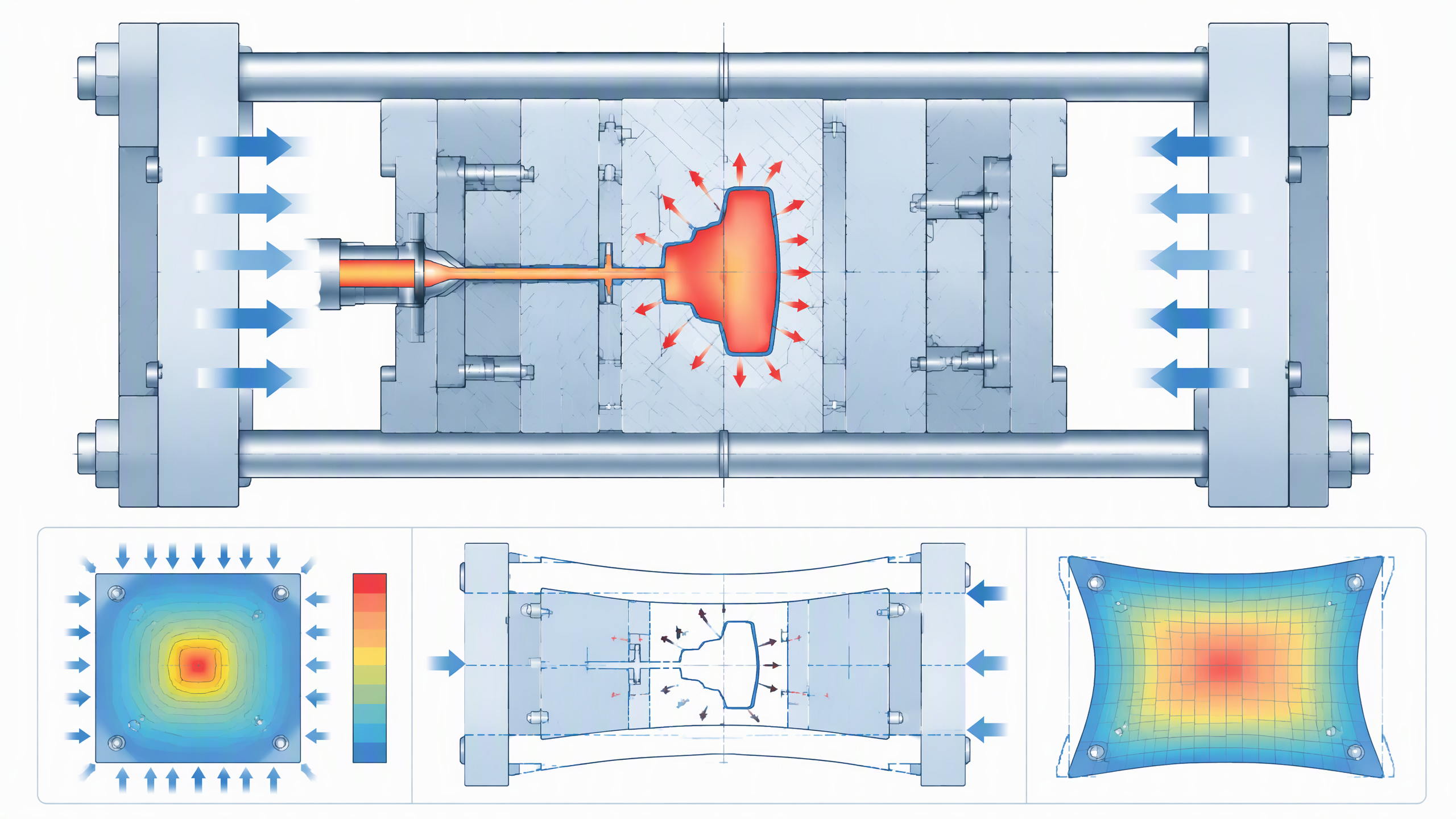
Clamping force, measured in metric tons (tonnes) or kilonewtons (kN), is the total force applied by the injection molding machine's clamping unit to keep the mold closed during the injection cycle. It must overcome two primary forces: the cavity pressure exerted by the molten plastic against the mold walls, and the mechanical resistance within the mold assembly itself.
The relationship is governed by a fundamental equation:
F = P × A
Where F is the required clamping force (kN), P is the cavity pressure (MPa), and A is the projected area of the molded part at the parting line (cm²). For example, if a part has a projected area of 300 cm² and the material requires a cavity pressure of 30 MPa (approximately 300 bar), the minimum clamping force needed is 9,000 N, or roughly 9 tons.
In practice, engineers apply a safety factor of 1.2 to 1.5 to account for process variability, material viscosity fluctuations, and mold temperature gradients. This means the actual machine selected should provide 11 to 14 tons of clamping force for this scenario.
Key Terminology Every Engineer Should Know
Projected Area: The two-dimensional shadow cast by the molded part onto the mold parting plane, including all cavities, runners, and gates. This is the surface area against which the cavity pressure acts to force the mold open.
Cavity Pressure: The internal pressure exerted by molten plastic against the mold cavity walls. It varies with material grade, melt temperature, injection speed, and part geometry. Cavity pressure is always lower than nozzle injection pressure due to flow resistance in the runner and gate.
Safety Factor (K): A multiplier applied to the theoretical clamping force to account for real-world process variability. Industry standard values range from 1.2 for well-characterized, stable processes to 1.5 for new molds or materials with high viscosity variation.
How to Calculate Injection Molding Clamping Force
Step 1: Determine the Projected Area
Measure the maximum projected area of the part at the parting line, including all cavities, runners, and cold slug wells. For a multi-cavity mold, sum the projected areas of all cavities plus the runner system. Computer-aided design (CAD) software typically provides this value automatically, but manual verification using the part drawing is recommended for critical applications.
Step 2: Determine the Cavity Pressure
Cavity pressure depends on the material being processed. According to data published by BASF and Dow Chemical in their respective molding guidelines, typical cavity pressures range as follows:
- Low-viscosity materials (PE, PP): 200–300 bar (20–30 MPa)
- Medium-viscosity materials (ABS, PS, nylon): 300–500 bar (30–50 MPa)
- High-viscosity materials (PC, PMMA, PEI): 500–800 bar (50–80 MPa)
These values represent the effective cavity pressure, not the injection pressure at the nozzle. The actual cavity pressure is always lower due to pressure losses in the runner system, gate, and flow path within the cavity itself.
Step 3: Apply the Safety Factor
The raw calculation F = P × A provides a theoretical minimum. Process engineers apply a safety factor (K) of 1.2 to 1.5:
Factual = K × P × A
This accounts for viscosity increases as melt temperature drops, flow resistance variations in complex geometries, mold deflection under load, and process window adjustments during production. For new molds or unfamiliar materials, the higher end of the range (1.4–1.5) is recommended.
Step 4: Select the Machine
Choose an injection molding machine whose rated clamping force exceeds Factual. Running a machine at 80% or less of its maximum clamping capacity is recommended to prolong equipment life and ensure consistent force application across the parting surface. Operating beyond 90% capacity risks clamp drift and inconsistent part quality over long production runs.
Practical Calculation Example
Consider a 4-cavity mold producing ABS connector housings:
- Each cavity projected area: 75 cm²
- Runner system projected area: 50 cm²
- Total projected area A = (4 × 75) + 50 = 350 cm²
- ABS cavity pressure P ≈ 40 MPa
- Safety factor K = 1.3
Factual = 1.3 × 40 MPa × 350 cm² = 18,200 N = approximately 130 tons. The selected machine should have a rated clamping force of at least 130 tons, ideally 150–160 tons to operate at approximately 80% capacity.
Factors Affecting Clamping Force Requirements
Material Properties
The viscosity of the molding material is the single most influential factor. High-viscosity engineering plastics such as polycarbonate (PC) and polyetherimide (PEI) demand significantly higher cavity pressures, directly increasing clamping force requirements. Glass-filled compounds add another layer of complexity, as the filler increases melt viscosity by 20–40% compared to unfilled grades, according to data from Sabic Innovative Plastics.
Part Geometry and Wall Thickness
Thin-walled parts—those with wall thicknesses below 1.0 mm—require injection pressures that can exceed 1,000 bar, dramatically increasing the clamping force needed. According to a study by the American Injection Molding Institute (AIM), reducing wall thickness from 2.0 mm to 0.8 mm can increase required clamping force by up to 250%.
Conversely, parts with large flat surfaces create high projected areas without proportional structural benefit, placing excessive demands on clamping capacity. Mold designers can mitigate this by incorporating coring and ribs to reduce projected area while maintaining structural integrity.
Mold Design Features
Runner system: Full hot runner systems reduce material waste but may increase the projected area contributing to clamping force requirements. The trade-off between material savings and clamp tonnage must be evaluated during the mold making phase.
Mold base rigidity: A well-designed mold base with adequate support pillars distributes clamping force evenly, preventing localized deflection. The standard ratio of support pillar spacing to plate thickness should not exceed 4:1 for P20 steel molds.
Parting line geometry: Irregular parting lines create uneven force distribution, requiring higher nominal clamping force to ensure adequate sealing at all points along the parting surface.
Process Parameters
Injection speed, melt temperature, and holding pressure all affect the cavity pressure profile. Higher injection speeds generate shear heating that temporarily lowers viscosity, potentially reducing clamping force needs. However, excessive speed can cause flash if the clamping force is marginally insufficient. The process window must be validated through systematic design of experiments (DOE).
Consequences of Insufficient Clamping Force
Flash Formation
Flash—the thin layer of plastic that escapes the mold parting line—is the most visible and common consequence of inadequate clamping force. Flash increases post-processing costs, degrades dimensional accuracy, and can damage the mold parting surfaces over time. In high-volume production, even a 0.05 mm flash condition across a multi-cavity mold can add thousands of dollars in trimming labor annually.
Dimensional Instability
When the mold opens slightly under injection pressure, the cavity volume increases unpredictably, leading to dimensional variation between shots. For precision components used in medical devices or automotive injection molding parts, this variation can render parts unusable. A study published in the Journal of Injection Molding Technology found that mold breathing as small as 0.02 mm can cause dimensional deviations exceeding 0.1 mm on critical features.
Mold Damage
Repeated mold breathing—the opening and closing of mold halves under marginal clamping force—causes accelerated wear on parting surfaces, alignment pins, and interlocks. Over thousands of cycles, this damage can require costly mold refurbishment, reducing overall equipment effectiveness (OEE) and increasing maintenance downtime.
Optimizing Clamping Force: Best Practices
Mold Flow Analysis
Before mold construction, engineers use mold flow analysis software such as Moldflow or Moldex3D to simulate cavity pressure distribution and identify potential flash zones. This simulation allows designers to optimize gate placement, runner sizing, and wall thickness to minimize required clamping force before steel is cut.
Machine Selection Strategy
Selecting a machine with 20–30% excess clamping capacity provides a process window for adjustments. However, oversized machines waste energy and increase cycle time due to slower clamp movement. The key is to match machine tonnage to calculated requirements with a reasonable margin. Modern electric and hybrid machines offer more precise clamping force control than traditional hydraulic machines, reducing the safety factor needed.
Regular Calibration
Clamping force can drift over time due to hydraulic system wear, toggle degradation, or mold base deformation. Regular calibration using strain gauges or pressure sensors ensures that the actual clamping force matches the machine's displayed value. Industry standards recommend calibration every 6 months or after 100,000 cycles, whichever comes first.

At Shiny Mold, our engineering team applies a rigorous clamping force optimization protocol for every new project. This includes mold flow simulation, projected area calculation, material-specific cavity pressure determination, and machine selection validated by first-article inspection. With over 23 years of experience in precision mold making and injection molding, we ensure that every part meets dimensional and aesthetic specifications without flash or mold damage.
Conclusion
Injection molding clamping force is far more than a machine specification—it is a critical engineering parameter that directly influences part quality, production efficiency, and tool longevity. By understanding the calculation methodology, the factors that affect it, and the consequences of getting it wrong, manufacturers can avoid costly defects and deliver consistent, high-quality molded products.
The principles outlined in this guide—accurate projected area measurement, material-specific cavity pressure data, appropriate safety factors, and machine selection with adequate margin—form the foundation of every successful injection molding program. For more insights on mold design, processing parameters, and quality optimization, explore our industry articles and FAQ sections.
Frequently Asked Questions (FAQ)
What is the formula for injection molding clamping force?
The basic formula is F = P × A, where F is the clamping force (in kN or tons), P is the cavity pressure (in MPa or bar), and A is the projected area of the part at the parting line (in cm²). A safety factor of 1.2–1.5 is then applied to account for process variability, giving Factual = K × P × A.
How much clamping force do I need for my part?
Calculate the projected area of your part (including runners for multi-cavity molds), multiply by the material's typical cavity pressure (200–800 bar depending on viscosity), and apply a 1.2–1.5 safety factor. For example, a 300 cm² ABS part at 400 bar with a 1.3 safety factor requires approximately 156 tons of clamping force.
What happens if clamping force is too low?
Insufficient clamping force causes flash, dimensional instability, and accelerated mold wear. Flash requires additional post-processing labor, while dimensional variation can make parts fail quality inspection. Over time, mold breathing damages parting surfaces and alignment features, leading to costly refurbishment.
Can clamping force be too high?
Yes. Excessive clamping force increases mold wear, consumes more energy, and can cause mold plate deflection that actually creates uneven part dimensions. It also reduces equipment lifespan and increases cycle time on hydraulic machines. The goal is to apply the minimum force that prevents flash with an appropriate safety margin of 20–30%.
How does part size affect clamping force?
Clamping force scales linearly with projected area. A part twice as large requires approximately twice the clamping force, assuming the same material and wall thickness. Large flat parts are particularly demanding because they maximize projected area without proportional structural advantage, so designers should consider coring to reduce the effective projected area.
What is the difference between clamping force and injection pressure?
Clamping force is applied by the machine to keep the mold closed (measured in tons or kN), while injection pressure is applied by the screw to push molten plastic into the cavity (measured in bar or MPa). Clamping force must overcome the cavity pressure generated by injection pressure to prevent the mold from opening during the injection and packing phases.