


Why Injection Molding Wall Thickness Determines Part Quality and Cost
Injection molding wall thickness is one of the most critical design parameters that directly influences part strength, cycle time, manufacturing cost, and end-product performance. Whether you are producing consumer electronics housings, automotive interior components, or medical device enclosures, getting wall thickness right from the design stage can mean the difference between a robust, cosmetically flawless part and one riddled with sink marks, warpage, and voids.
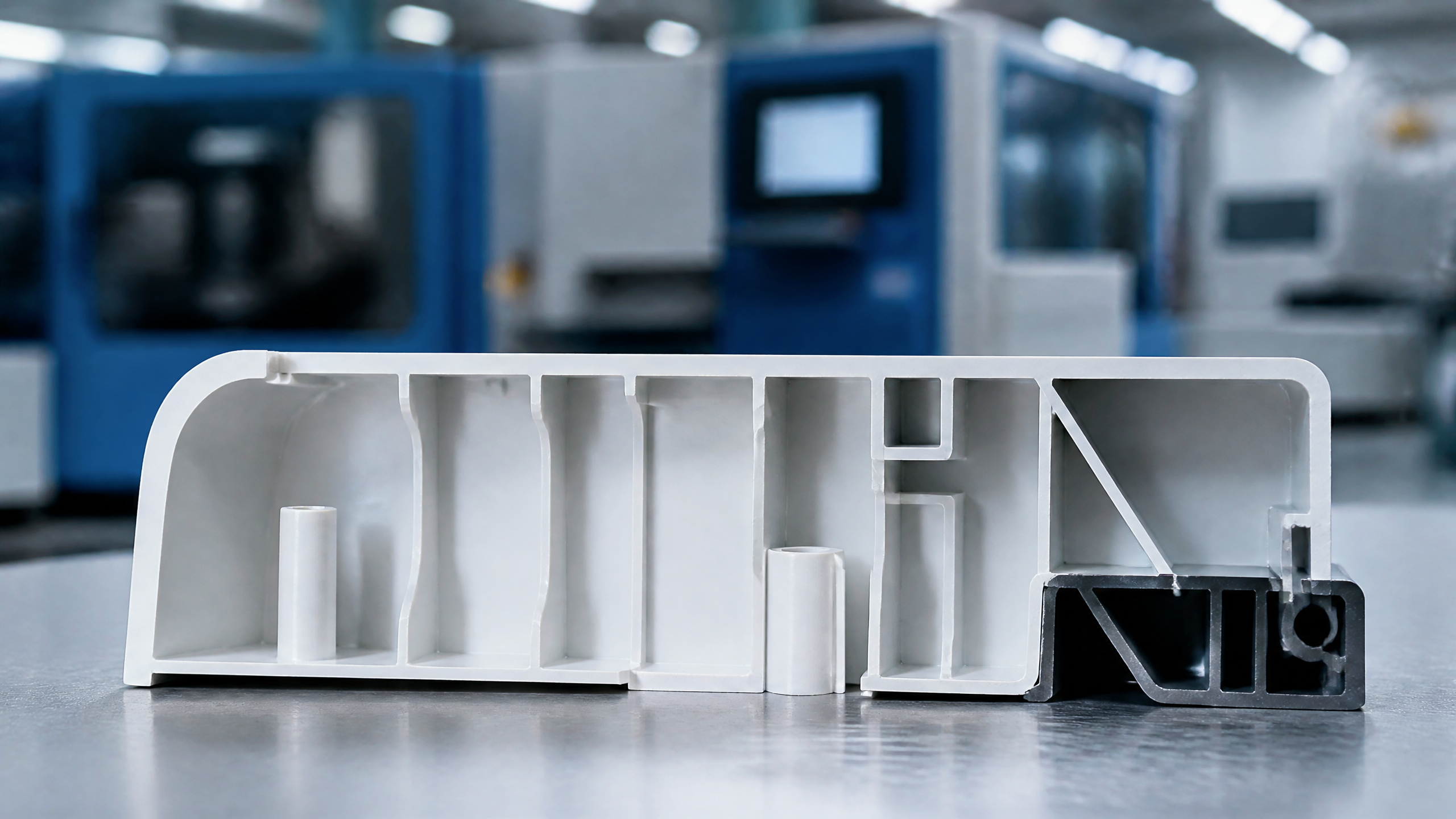
At Shiny Mold, our engineering team has spent over 15 years optimizing wall thickness for thousands of custom injection molding projects. We have seen firsthand how a seemingly minor thickness adjustment of 0.2 mm can reduce cycle time by 8 seconds, saving manufacturers tens of thousands of dollars annually. According to the Society of Plastics Engineers (SPE), wall thickness decisions affect up to 70% of total part cost, making it the single highest-leverage design choice in the entire molding process.
Fundamental Principles of Wall Thickness Design
Uniform Wall Thickness: The Golden Rule
The foundational principle of injection molding wall thickness design is maintaining uniform thickness throughout the part. When wall sections vary significantly, molten plastic cools at different rates across the part, creating internal stresses that lead to injection molding defects such as warpage, sink marks, and dimensional instability. The goal is to keep all walls within approximately 10% of the nominal thickness.
Uniform thickness ensures that melt flow front moves evenly, cooling progresses uniformly, and residual stress distribution remains balanced. When engineers at our mold making facility run mold flow analysis, the first parameter we validate is wall thickness uniformity—because no amount of process optimization can compensate for fundamentally poor wall design.
Material-Specific Thickness Ranges
Different thermoplastic materials require different wall thickness ranges based on their melt viscosity, shrinkage rates, and thermal conductivity. Below is a practical reference for common injection molding materials:
- ABS: 1.2–3.0 mm (optimal 1.5 mm)
- Polycarbonate (PC): 1.5–5.0 mm (optimal 2.0 mm)
- PP (Polypropylene): 0.8–3.5 mm (optimal 2.0 mm)
- Nylon (PA66): 1.0–3.5 mm (optimal 1.5 mm)
- POM (Acetal): 1.0–3.0 mm (optimal 1.5 mm)
- HDPE: 0.8–3.0 mm (optimal 1.5 mm)
- PC/ABS Blend: 1.2–3.5 mm (optimal 2.0 mm)
These ranges reflect industry-standard data published by material suppliers such as BASF, Dow, and SABIC. Exceeding the upper limit dramatically increases cooling time and risk of internal voids, while going below the lower limit can cause short shots, where melt flow freezes before filling the cavity.
Critical Design Rules for Wall Thickness Transitions

Gradual Transitions
When a part design absolutely requires a change in wall thickness, the transition must be gradual rather than abrupt. The industry standard is a taper ratio of 1:3 (a 3:1 slope), meaning that for every 1 mm of thickness change, the transition should extend over at least 3 mm in length. Abrupt thickness changes create stress concentration points, flow turbulence, and visible surface blemishes.
Rib Design and Wall Thickness Relationship
Ribs are structural reinforcements added to increase part stiffness without adding excessive material. However, ribs introduce a secondary wall that intersects the primary wall, creating a local thick section at the junction. To prevent sink marks on the opposite surface, rib thickness should not exceed 50–60% of the nominal wall thickness. This is one of the most commonly violated rules we encounter during design for manufacturability (DFM) reviews at Shiny Mold.
Additional rib design guidelines include:
- Rib height should not exceed 3× the nominal wall thickness
- Rib draft angle should be at least 0.5 degrees per side for easy ejection
- Corner radii at the rib base should be 0.25–0.5 mm to reduce stress concentration
- Space between parallel ribs should be at least 2× the wall thickness
Boss and Stud Design
Bosses are cylindrical features used for fastening or alignment. Like ribs, a boss creates a local thick section. The outer diameter of a boss should not exceed 2.5–3× the hole diameter, and the wall thickness around the boss should match the nominal wall. When bosses are located near a wall, connect them with a rib rather than placing the boss directly against the wall to avoid creating an excessively thick junction.
How Wall Thickness Affects Manufacturing Outcomes
Cooling Time and Cycle Time
Cooling time accounts for approximately 60–75% of the total injection molding cycle. The relationship between wall thickness and cooling time follows a squared function: doubling the wall thickness quadruples the cooling time. This is described by the Fourier number equation, where cooling time is proportional to the square of the maximum wall thickness divided by the thermal diffusivity of the material.
For example, increasing wall thickness from 2.0 mm to 3.0 mm increases cooling time by approximately 2.25×. For a part running on a 30-second cycle, this change alone could push cycle time to 45+ seconds, reducing hourly output by 33%. Over a production run of 100,000 parts, the cost implications are significant.
Shrinkage and Dimensional Accuracy
Thicker walls shrink more than thinner walls because more material volume contracts during cooling. Mold shrinkage values for common materials range from 0.3% for glass-filled materials to 5.0% for PP. When wall thickness varies across a part, differential shrinkage creates internal stresses that cause the part to warp or distort after ejection.
Our engineering team uses precision mold making techniques combined with mold flow simulation to predict and compensate for differential shrinkage. We adjust the steel dimensions (mold shrinkage compensation) based on both material data sheets and empirical measurements from previous production runs.
Surface Quality
Wall thickness directly impacts surface finish quality. Thin walls can cause flow marks and hesitation lines, while thick walls are prone to sink marks and blush. For high-cosmetic parts requiring Class A surfaces, maintaining uniform thickness and keeping features like ribs below 50% of the wall thickness is essential to achieving defect-free surfaces.
Common Defects Caused by Improper Wall Thickness
Sink Marks
Sink marks are localized depressions on the part surface, typically occurring opposite thick sections such as ribs, bosses, or thick wall junctions. They form when the outer skin solidifies while the core is still molten and shrinking, pulling the surface inward. Keeping rib thickness at 50% of the wall and adding targeted cooling channels near thick sections are the primary countermeasures.
Warpage
Warpage results from non-uniform shrinkage across the part. When one section cools and shrinks faster than another, differential stresses build up and cause the part to deform. Thinner sections freeze first and set the part geometry, while thicker sections continue shrinking, pulling the part out of shape. This is particularly common in flat panels with varying thickness or asymmetric designs.
Voids
Internal voids form when the outer surface of a thick section solidifies before the core, and the shrinking core material pulls away from itself, creating a vacuum pocket. These are often invisible on the surface but can compromise structural integrity. Voids are most common in sections exceeding 4–5 mm in thickness for most materials.
Short Shots
Conversely, walls that are too thin can cause short shots, where the melt freezes before completely filling the mold cavity. This is especially problematic for high-flow-length-to-thickness ratios, long thin sections, or parts with complex geometries that restrict flow.
Best Practices for Optimizing Wall Thickness

Start with DFM Analysis
The most effective approach is to begin wall thickness optimization during the design for manufacturability (DFM) phase. At Shiny Mold, we conduct DFM reviews with every client, using mold flow analysis software (Moldflow and Moldex3D) to simulate melt flow, predict potential defects, and recommend thickness adjustments before steel is ever cut.
Consider Functional Requirements First
Before reducing wall thickness for cost savings, evaluate the functional requirements of the part. Does it need to withstand impact loads? Does it require structural rigidity? Does it need to house internal components with specific clearance? The minimum functional thickness should be determined before optimizing for manufacturability.
Balancing Cost and Performance
The optimal wall thickness balances material cost, cycle time, tooling complexity, and part performance. While thinner walls reduce material usage and cycle time, they may require more complex mold features (such as additional gates or venting) and can increase the risk of defects. Our FAQ section provides additional guidance on cost-performance trade-offs in injection molding design.
Conclusion
Injection molding wall thickness is far more than a dimensional specification—it is the foundation upon which part quality, production efficiency, and manufacturing economics are built. By adhering to the principles of uniform thickness, material-specific ranges, gradual transitions, and proper rib and boss design, manufacturers can dramatically reduce defect rates, shorten cycle times, and lower overall production costs.
The Shiny Mold Engineering Team recommends involving your molding partner early in the design process. A thorough DFM review with mold flow analysis can identify potential wall thickness issues before tooling investment, saving both time and money. With over 15 years of experience in custom injection molding and precision mold making, we have helped clients across automotive, medical, consumer electronics, and industrial sectors achieve optimal wall thickness designs for millions of parts.
Frequently Asked Questions (FAQ)
What is the standard wall thickness for injection molded parts?
The standard wall thickness for injection molded parts typically ranges from 1.0 mm to 3.0 mm, with 1.5–2.0 mm being the most common for general-purpose applications. However, the optimal thickness depends on the specific material, part size, functional requirements, and cosmetic standards. Thin-wall molding can achieve walls as thin as 0.5 mm for specialized applications.
What happens if injection molding wall thickness is too thick?
Excessively thick walls increase cooling time dramatically (cooling time is proportional to the square of thickness), raise material costs, and increase the risk of defects such as sink marks, voids, and internal porosity. Thick sections also develop greater shrinkage, leading to dimensional instability and warpage.
What is the minimum wall thickness for injection molding?
The minimum wall thickness depends on the material and flow length. For most engineering plastics, 0.8 mm is a practical minimum for short flow lengths, while 1.0–1.2 mm is recommended for parts with longer flow paths. Materials with higher melt flow indices (such as PP and HDPE) can achieve thinner walls than highly viscous materials like polycarbonate.
How do you transition between different wall thicknesses?
Use a gradual taper with a minimum 3:1 ratio (3 mm length for every 1 mm of thickness change). Avoid abrupt steps or sharp corners at transitions, as these create stress concentrations and flow disruptions. Blend transitions smoothly and use generous radii at all corners.
How thick should ribs be relative to the main wall?
Ribs should be 50–60% of the nominal wall thickness to prevent sink marks on the opposite surface. For a 2.0 mm wall, ribs should be 1.0–1.2 mm thick. This ratio ensures adequate structural reinforcement while minimizing the thick section at the rib-wall junction.
Authored by the Shiny Mold Engineering Team. Shiny Mold is a custom injection molding and precision mold manufacturer based in Dongguan, China, serving global clients in automotive, medical, electronics, and industrial markets. For technical inquiries or project consultations, contact our engineering team.


