By Shiny Mold Engineering Team | October 2, 2026
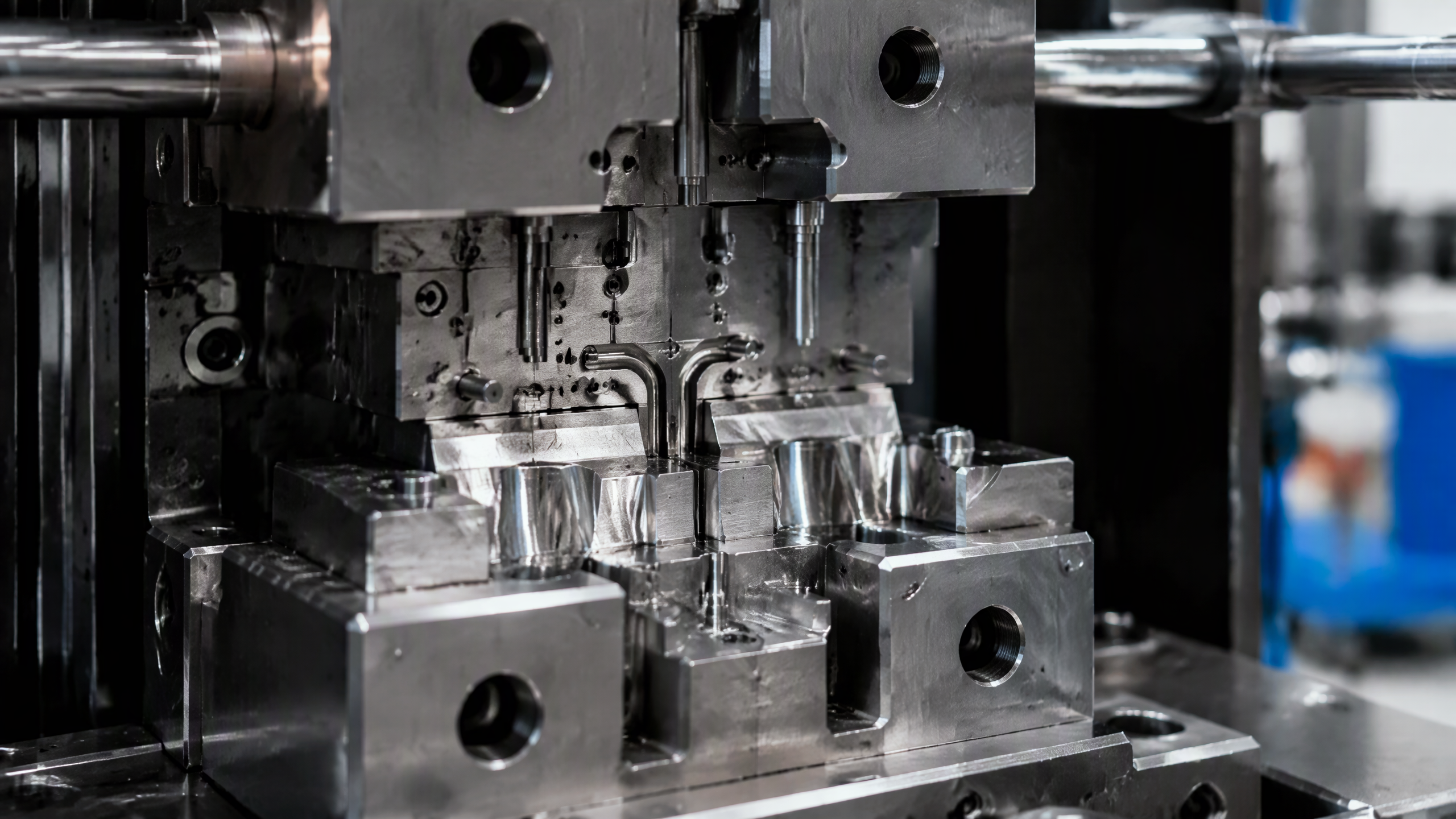
Injection molding clamping force is the foundational parameter that determines whether a molded part will be defect-free or plagued by flash, short shots, and dimensional instability. It is the mechanical pressure, measured in kilonewtons (kN) or tons, that an injection molding machine applies to keep the two halves of a mold tightly closed during the injection and packing phases. When this force is insufficient, the internal cavity pressure generated by molten plastic will force the mold halves apart, causing flash along the parting line and compromising part accuracy. When the force is excessive, it wastes energy, accelerates mold wear, and can deform thin-wall sections. Understanding how to calculate, optimize, and control clamping force is therefore essential for any engineer involved in injection molding production.

According to a 2025 industry report by Grand View Research, the global injection molded plastics market was valued at approximately USD 265.1 billion in 2024 and is projected to reach USD 434.5 billion by 2030, growing at a CAGR of 8.74%. With millions of tons of plastic parts produced annually, even a small percentage improvement in clamping force optimization translates to enormous cost savings and waste reduction across the manufacturing supply chain. At Shiny Mold, our engineering team has spent over 23 years optimizing clamping force parameters for automotive, medical, and consumer electronics applications, and this guide distills that practical experience into actionable engineering principles.
What Is Injection Molding Clamping Force?
Clamping force is the counter-force applied by the injection molding machine's clamping unit to oppose the separating force created by the molten plastic inside the mold cavity. During the injection phase, plastic melt is forced into the cavity under pressures typically ranging from 500 to 1,800 bar (50 to 180 MPa). This melt pressure acts on the projected area of the part and runner system, generating a force that tries to push the mold open. The machine's clamping force must exceed this separating force at all times to maintain mold integrity.
The Physics Behind Clamping Force
The fundamental relationship governing injection molding clamping force is straightforward but carries critical engineering implications. The cavity pressure force (the force attempting to open the mold) equals the average cavity pressure multiplied by the projected area of the molded part and runner system. The machine's clamping force must be greater than this cavity pressure force, typically by a safety factor of 1.1 to 1.3, to account for pressure spikes, viscosity variations, and process fluctuations.

The projected area is defined as the two-dimensional area of the part and runner system projected onto a plane perpendicular to the mold opening direction. For a flat circular part with a diameter of 200 mm, the projected area would be approximately 31,416 mm² (pi times the radius squared). If the cavity pressure at the end of fill is 60 MPa, the resulting cavity pressure force would be 60 MPa times 31,416 mm², which equals approximately 1,885 kN. Applying a safety factor of 1.2, the required clamping force would be approximately 2,262 kN, or roughly 226 tons. This calculation is fundamental to mold making and machine selection.
How to Calculate Injection Molding Clamping Force
The standard formula for calculating the required clamping force is:
Fc = P times Ap times SF
Where Fc is the required clamping force (kN), P is the average cavity pressure (MPa), Ap is the total projected area including runners and gates (mm² or cm²), and SF is the safety factor (typically 1.1 to 1.3).
Determining Cavity Pressure
Cavity pressure is not a single fixed value; it varies throughout the injection cycle and across the mold geometry. The critical value for clamping force calculation is the peak pressure at the end of the filling and packing phase. This value depends on several factors including material viscosity, melt temperature, injection speed, wall thickness, and flow length. Amorphous thermoplastics such as ABS and polycarbonate generally require lower cavity pressures (30 to 60 MPa), while semi-crystalline materials like nylon and POM may require 50 to 100 MPa. Glass-filled or mineral-filled compounds can demand even higher pressures due to increased melt viscosity.
Calculating Projected Area
The projected area must include all features of the part visible from the parting plane, plus the runner and gate system if they are on the same side of the mold parting line. For multi-cavity molds, the total projected area is the sum of all cavities and the shared runner system. Engineers must also consider that complex geometries with deep ribs or tall cores may have effective projected areas larger than the simple two-dimensional silhouette, as side cores and lifters can introduce additional separating forces. For more details on how projected area interacts with injection molding industry practices, our technical resources provide case studies from real production environments.
Applying the Safety Factor
The safety factor accounts for process variability and pressure spikes that occur during normal production. A safety factor of 1.1 is appropriate for well-characterized, stable processes with amorphous materials and simple geometries. For semi-crystalline materials, multi-cavity molds, or parts with long flow paths, a safety factor of 1.2 to 1.3 is recommended. In practice, many molding shops use a rule of thumb of 2 to 4 tons of clamping force per square inch of projected area for general-purpose molding, though this should always be verified with proper calculations.
Factors Affecting Clamping Force Requirements
Material Selection and Viscosity
The melt viscosity of the plastic resin directly influences the cavity pressure needed to fill the mold. Low-viscosity materials such as polyethylene and polypropylene flow more easily and generate lower cavity pressures, reducing the required clamping force. High-viscosity engineering resins like polycarbonate, PEEK, and glass-filled nylon require higher injection pressures, which in turn demand greater clamping force. The melt flow index (MFI) is a useful indicator: resins with higher MFI values generally require less clamping force. Our team at Shiny Mold always conducts thorough material analysis during the mold design FAQ consultation phase to ensure proper machine selection.
Part Geometry and Wall Thickness
Thinner walls require higher injection pressures to fill before the melt solidifies, increasing cavity pressure and clamping force requirements. A part with 0.8 mm walls may need 30 to 50 percent more clamping force than the same geometry with 2.0 mm walls. Large flat parts present a large projected area with relatively low stiffness, making them particularly susceptible to flash if clamping force is marginal. Conversely, parts with deep draws, tall ribs, or complex core structures may concentrate separating forces in specific regions, requiring localized clamping force analysis.
Mold Design and Flow Length
The distance that molten plastic must travel from the gate to the farthest point of the cavity (flow length) significantly impacts pressure requirements. Longer flow paths result in greater pressure drops, meaning the pressure at the gate must be higher to achieve adequate filling at the end of the flow path. This higher gate pressure directly increases the average cavity pressure and thus the required clamping force. Hot runner systems can reduce flow length pressure losses compared to cold runners, while optimized gate placement can minimize the maximum flow path. Mold flow analysis software, as discussed in our injection mold design guide, is invaluable for predicting these pressure distributions before steel is cut.
Processing Parameters
Injection speed, melt temperature, mold temperature, and packing pressure all influence the effective cavity pressure. Higher injection speeds generate shear heating that can reduce viscosity but may also create pressure spikes at the end of fill. Higher melt and mold temperatures reduce viscosity and pressure requirements but increase cycle time. Packing pressure, applied after the cavity is filled, is typically 50 to 80 percent of the injection pressure and must also be resisted by the clamping force. The key principle is that the clamping force must exceed the peak cavity pressure at every point during the cycle.
Consequences of Incorrect Clamping Force
Insufficient Clamping Force
When clamping force is too low, the most immediate and visible consequence is flash formation. Flash is excess plastic material that escapes through the parting line, creating thin, unwanted fins of material on the molded part. Flash not only degrades part appearance but also increases post-molding labor for deflashing and can interfere with assembly tolerances. In severe cases, insufficient clamping force can cause the mold to open slightly during injection, leading to dimensional variation, excessive part weight, and even damage to the mold parting line surfaces. The cost of flash-related defects in the global injection molding industry is estimated at hundreds of millions of dollars annually in scrap, rework, and labor.
Excessive Clamping Force
While it may be tempting to simply use the largest available machine, excessive clamping force carries its own penalties. Over-clamping can cause excessive vent compression, trapping air and gas in the cavity, leading to burn marks, short shots, or diesel effect discoloration. It also accelerates wear on mold parting lines, guide pins, and bushings, increasing maintenance costs and reducing mold life. In extreme cases, over-clamping can cause deformation of the mold plates themselves, particularly in large molds with thin plate sections, resulting in uneven part dimensions and potential mold damage. Energy consumption also increases proportionally with clamping force, raising both operating costs and carbon footprint.

Optimizing Clamping Force in Production
Machine Selection Strategy
Selecting the right injection molding machine tonnage begins with the calculated clamping force requirement plus the safety factor. However, machine selection should also consider the mold size, tie-bar spacing, shot size capacity, and plasticizing rate. A machine that is too small will produce defective parts, while a machine that is too large wastes energy and may cause mold damage. The optimal approach is to select a machine whose maximum clamping force is 10 to 20 percent above the calculated requirement, providing a buffer for process optimization without excessive over-capacity.
Process Monitoring and Control
Modern injection molding machines equipped with closed-loop clamping force control can maintain a constant clamping force throughout the cycle, compensating for thermal expansion of the mold and machine components. In-mold pressure sensors provide real-time cavity pressure data that can be used to fine-tune clamping force settings. The trend in the industry, as noted by the Society of Plastics Engineers (SPE), is toward adaptive clamping force control systems that automatically adjust force based on cavity pressure feedback, reducing energy consumption by 10 to 20 percent while maintaining part quality.
Mold Design Considerations
Several mold design strategies can reduce the required clamping force. Balanced runner layouts distribute melt pressure more evenly across cavities, reducing peak cavity pressure. Optimized gate locations minimize maximum flow length and pressure requirements. Parting line vent design ensures proper air evacuation without requiring excessive clamping force to seal the mold. Interlock features such as tapered interlocks or parting line locks can help maintain mold alignment under marginal clamping force conditions. For high-cavitation molds, sequential valve gating can reduce the simultaneous cavity pressure load by filling cavities in stages rather than simultaneously.
Summary: Key Takeaways for Engineers
Injection molding clamping force is a critical engineering parameter that directly impacts part quality, production efficiency, and mold longevity. The key principles are: calculate the required force using the projected area and cavity pressure with an appropriate safety factor; select a machine with 10 to 20 percent excess capacity; monitor and control clamping force during production using modern closed-loop systems; and optimize mold design to minimize pressure requirements. By following these principles, manufacturers can reduce defect rates, extend mold life, and lower energy consumption. At Shiny Mold, our engineering team applies these principles across every project, from automotive components to medical devices, ensuring that each mold is matched to the optimal machine and process parameters.
Frequently Asked Questions (FAQ)
What is the standard formula for calculating injection molding clamping force?
The standard formula is: Clamping Force = Cavity Pressure times Projected Area times Safety Factor. Cavity pressure is typically 30 to 100 MPa depending on the material, projected area is measured in square millimeters or centimeters including runners, and the safety factor ranges from 1.1 to 1.3. For example, a part with 20,000 mm² projected area molded at 60 MPa cavity pressure with a safety factor of 1.2 requires approximately 1,440 kN of clamping force.
How much clamping force do I need per square inch of projected area?
A common industry rule of thumb is 2 to 4 tons of clamping force per square inch of projected area. The lower end (2 tons) applies to low-viscosity amorphous materials with simple geometries, while the higher end (4 tons) applies to high-viscosity semi-crystalline or filled materials with complex geometries. This rule should always be verified with actual cavity pressure data and material specifications.
What happens if clamping force is too low?
Insufficient clamping force causes the mold to open slightly during injection, resulting in flash formation along the parting line. This leads to dimensional variation, excessive part weight, degraded surface appearance, and increased post-molding labor for deflashing. In severe cases, it can damage the mold parting line surfaces and require costly rework.
Can too much clamping force damage the mold?
Yes. Excessive clamping force compresses vents, traps air and gas, causes burn marks and short shots. It also accelerates wear on guide pins, bushings, and parting line surfaces, and can deform mold plates, particularly in large molds with thin plate sections. Energy consumption also increases proportionally with clamping force.
How does part wall thickness affect clamping force requirements?
Thinner walls require higher injection pressures to fill the cavity before the melt solidifies, which increases cavity pressure and thus the required clamping force. A part with 0.8 mm walls may require 30 to 50 percent more clamping force than the same geometry with 2.0 mm walls. This is why thin-wall molding applications, such as electronic device housings, often require high-tonnage machines.
What is the difference between clamping force and injection pressure?
Clamping force is the mechanical force (in kN or tons) applied by the machine to keep the mold closed, while injection pressure is the hydraulic or electric force (in bar or MPa) that pushes the molten plastic into the mold cavity. Clamping force opposes the separating force created by injection pressure acting on the projected area of the part.
How do I reduce the required clamping force for my mold?
Strategies include using low-viscosity materials or higher melt temperatures, optimizing gate placement to reduce flow length, employing balanced runner designs, using hot runner systems, reducing part projected area through design optimization, and implementing sequential valve gating for multi-cavity molds. Mold flow analysis can identify the most effective strategies for a specific application.