Introduction to Injection Molding Shrinkage
Injection molding shrinkage is one of the most critical dimensional phenomena that engineers must account for when designing plastic parts and manufacturing precision molds. Every thermoplastic material contracts as it transitions from a molten state to a solid state inside the mold cavity, and this contraction — typically ranging from 0.2% to 2.5% depending on the resin — directly determines whether a finished part meets dimensional tolerances or falls out of specification. For manufacturers producing high-volume components for the automotive, medical, and consumer electronics sectors, understanding and controlling shrinkage is not optional; it is a fundamental engineering requirement that separates a production-ready mold from one that requires costly rework.
At Shiny Mold, our engineering team has spent over 23 years compensating for material shrinkage across thousands of mold builds. This guide distills the practical knowledge we have accumulated — from material selection and mold design to processing parameter optimization and post-molding quality inspection — into a comprehensive reference for design engineers, tooling managers, and production planners seeking to minimize shrinkage-related defects.
What Is Injection Molding Shrinkage?
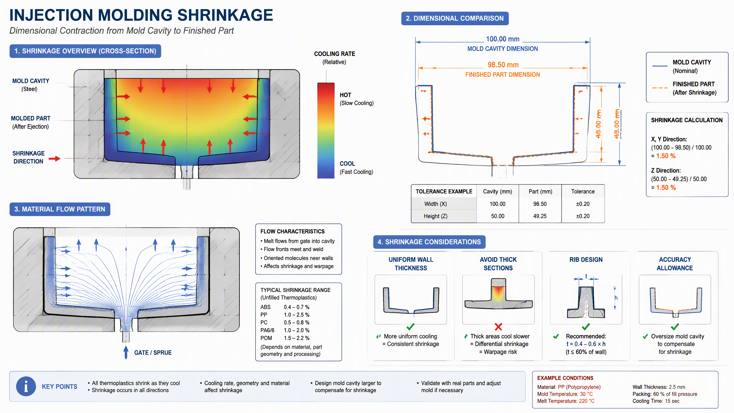
Injection molding shrinkage refers to the reduction in a plastic part's dimensions that occurs as the molten polymer cools, solidifies, and contracts within the mold cavity. According to ISO 294-4, shrinkage is defined as the difference between the mold cavity dimension and the corresponding dimension of the molded part, measured under standard conditions at least 24 hours after molding. The standard formula is:
S = (Lmold − Lpart) / Lmold × 100%
where S is the shrinkage rate, Lmold is the cavity dimension, and Lpart is the final part dimension. For example, if a mold cavity measures 100.00 mm and the finished part measures 98.50 mm, the shrinkage rate is 1.50%. This value becomes the baseline compensation factor that mold designers apply when sizing the cavity — they intentionally oversize the steel to account for the expected material contraction.
Isotropic vs. Anisotropic Shrinkage
Not all shrinkage is uniform. Amorphous thermoplastics such as ABS, polystyrene (PS), and polycarbonate (PC) tend to shrink more isotropically — that is, relatively equally in all directions — because their molecular chains are randomly oriented. Crystalline and semi-crystalline resins such as polypropylene (PP), polyamide (PA6/6), and acetal (POM) exhibit anisotropic shrinkage, meaning they contract differently depending on the direction of polymer flow. This is because crystalline regions form ordered structures that contract more tightly than amorphous regions, and the flow-induced molecular orientation causes additional differential shrinkage along the flow direction versus the transverse direction.
This anisotropic behavior is one of the leading causes of warpage in molded parts. When one region shrinks more than another — due to material orientation, wall thickness variation, or differential cooling — internal stresses build up and the part distorts. Engineers addressing these challenges can find additional guidance in our mold making services resource, which covers precision cavity machining and tolerance management.
Material-Specific Shrinkage Rates
Different thermoplastic resins exhibit markedly different shrinkage characteristics. The table below summarizes typical shrinkage ranges for commonly molded materials, based on data from resin manufacturers' technical data sheets and verified against production measurements at our facility:
| Material | Type | Typical Shrinkage (%) | Shrinkage Behavior |
|---|---|---|---|
| ABS | Amorphous | 0.4 – 0.7 | Isotropic |
| Polycarbonate (PC) | Amorphous | 0.5 – 0.8 | Isotropic |
| Polypropylene (PP) | Semi-crystalline | 1.0 – 2.5 | Anisotropic |
| Nylon 6/6 (PA66) | Semi-crystalline | 1.0 – 2.0 | Anisotropic |
| Acetal (POM) | Semi-crystalline | 1.5 – 2.2 | Anisotropic |
| Glass-filled Nylon (PA66-GF30) | Semi-crystalline (filled) | 0.2 – 0.5 | Highly anisotropic |
Note that glass fiber reinforcement dramatically reduces shrinkage in the flow direction — sometimes by more than 80% — but can increase shrinkage in the transverse direction. This is because glass fibers align with the flow front and restrict contraction along their axis, while the perpendicular direction remains largely unreinforced. Engineers at Shiny Mold routinely account for this behavior when designing molds for glass-filled applications in our industry projects.
Key Factors Affecting Shrinkage
1. Material Composition and Crystallinity
The single most influential factor is the resin itself. Semi-crystalline polymers undergo a phase transition from an ordered crystalline solid to a disordered melt and back again. This phase change involves a greater volumetric contraction than the simple thermal contraction seen in amorphous polymers. For example, PP can shrink up to 2.5%, while ABS typically stays below 0.7%. Reinforcements, fillers, and additives further modify this baseline — glass fibers, mineral fillers, and carbon fiber all reduce net shrinkage by constraining the polymer matrix.
2. Packing Pressure and Hold Time
During the injection molding cycle, after the cavity is filled, the machine applies packing (hold) pressure to compensate for the volume loss as the melt cools. Insufficient packing pressure results in excessive shrinkage and potential sink marks; excessive packing can cause flash, internal stress, or even mold deflection. The optimal packing pressure is typically 50–80% of the injection pressure, held until the gate freezes off. Gate freeze time — the moment when the material at the gate has solidified enough to prevent further material from entering or leaving the cavity — is the critical cutoff; packing pressure applied after gate freeze has no effect on shrinkage.
3. Mold Temperature
Mold temperature affects how quickly the polymer cools and crystallizes. A higher mold temperature promotes slower cooling, which allows more complete crystallization in semi-crystalline resins and therefore increases shrinkage. Conversely, a lower mold temperature results in faster cooling, which suppresses crystallization and reduces shrinkage — but at the cost of higher internal stress and potential warpage. Mold temperature control is therefore a delicate balance, typically maintained within ±2°C using precision chiller circuits machined into the precision mold base.
4. Melt Temperature
Higher melt temperatures increase the thermal delta between the molten and solid states, which can increase volumetric shrinkage. However, higher melt temperatures also reduce melt viscosity, allowing better packing and more complete cavity fill, which can offset shrinkage in thin-wall sections. The interplay between melt temperature, injection speed, and packing pressure is complex, which is why mold flow analysis software such as Moldflow or Moldex3D is routinely used during the design phase to predict shrinkage distribution before steel is cut.
5. Wall Thickness and Part Geometry
Thicker walls shrink more than thin walls because the core of a thick section cools more slowly, allowing greater crystallization and contraction. Variations in wall thickness across a single part create differential shrinkage, which is the primary cause of warpage. The best practice is to maintain uniform wall thickness throughout the part, with transitions tapered at 30–60° rather than abrupt steps. Rib thickness should not exceed 50–60% of the nominal wall to avoid sink marks on the opposite surface.
Mold Design Strategies for Shrinkage Compensation
Compensating for injection molding shrinkage begins at the mold design stage. The cavity must be intentionally oversized so that after the material shrinks, the part lands within the specified tolerance. This requires the mold designer to apply a shrinkage allowance — typically the material's nominal shrinkage rate plus a safety factor — to every cavity dimension. For a part designed at 100 mm nominal with a material shrinkage of 1.5%, the cavity would be cut at 100 / (1 − 0.015) = 101.52 mm.
However, this simple calculation assumes uniform isotropic shrinkage, which is rarely the case for semi-crystalline materials. In practice, experienced mold designers adjust the shrinkage allowance directionally — applying a higher allowance in the flow direction and a lower one in the transverse direction for glass-filled resins. This is where the expertise of the Shiny Mold Engineering Team becomes critical: with over two decades of empirical data from thousands of production molds, we can predict shrinkage behavior with a precision that software alone cannot achieve.
Another key design strategy is conformal cooling — cooling channels that follow the contour of the cavity surface to achieve uniform temperature distribution. Conformal cooling, enabled by metal 3D printing or baffle/blade inserts, can reduce differential cooling and the resulting differential shrinkage by up to 40% compared to traditional straight-line drilled channels. For parts with critical flatness or parallelism requirements, this can be the difference between a first-shot approval and weeks of mold trials.
Post-Molding Shrinkage and Dimensional Stability
Shrinkage does not stop when the part is ejected from the mold. Post-molding shrinkage — also called continued shrinkage or aging shrinkage — occurs as the polymer continues to crystallize and relax internal stresses over hours, days, or even weeks after molding. For semi-crystalline materials like PA66, post-molding shrinkage can account for an additional 0.1–0.3% dimensional change. This is why ISO 294-4 specifies that dimensional measurements should be taken at least 24 hours after molding, and why critical-tolerance parts should be conditioned or annealed before final inspection.

Environmental factors also play a role. Moisture absorption in nylon parts can cause dimensional swelling that partially offsets molding shrinkage. Thermal expansion and contraction during service can introduce cyclic dimensional changes. For applications requiring long-term dimensional stability — such as precision medical device housings or automotive sensor brackets — engineers should specify materials with low moisture absorption and low coefficient of thermal expansion (CTE), and design tolerances that accommodate the full dimensional envelope over the part's service life. Our FAQ section provides additional information on material selection for specific applications.
Measuring and Validating Shrinkage in Production
Validating that a molded part's dimensions fall within tolerance requires precision measurement equipment and a systematic inspection protocol. At Shiny Mold, every production run undergoes first-article inspection (FAI) using coordinate measuring machines (CMM) with probe accuracy of ±2.0 µm, digital calipers with 0.01 mm resolution, and optical comparators for complex geometries. Critical dimensions are compared against the CAD nominal and the tolerance band, and any deviation exceeding the acceptable range triggers a mold adjustment cycle.
Statistical process control (SPC) charts track dimensional trends across production runs, allowing engineers to detect gradual drift before it results in out-of-tolerance parts. Cpk values of 1.33 or higher are maintained for critical-to-quality (CTQ) dimensions. When shrinkage-related drift is detected, the first response is typically a processing adjustment — increasing packing pressure, extending hold time, or adjusting mold temperature — before resorting to mold steel changes. This data-driven approach ensures that dimensional control is achieved efficiently and with minimal downtime.
Frequently Asked Questions About Injection Molding Shrinkage
What causes injection molding shrinkage?
Injection molding shrinkage is caused by the thermal contraction of the polymer as it cools from its molten state to a solid state inside the mold cavity. Semi-crystalline materials shrink more than amorphous materials because they undergo a phase transition that involves additional volumetric contraction. The degree of shrinkage is influenced by material composition, packing pressure, mold temperature, melt temperature, wall thickness, and part geometry.
How much does plastic shrink in injection molding?
Shrinkage varies by material: amorphous resins like ABS and PC typically shrink 0.4–0.8%, while semi-crystalline resins like PP and PA66 can shrink 1.0–2.5%. Glass-filled materials shrink less, typically 0.2–0.5% in the flow direction. The exact value depends on processing conditions and part geometry, and should be verified using material data sheets and mold flow analysis.
Can injection molding shrinkage be eliminated?
No, shrinkage cannot be eliminated entirely — it is an inherent property of thermoplastic materials. However, it can be controlled and compensated for through mold design (oversizing the cavity), processing optimization (packing pressure, cooling time), material selection (using filled or low-shrinkage grades), and post-molding conditioning (annealing). The goal is to predict and manage shrinkage so that the finished part falls within the required tolerance.
What is the difference between shrinkage and warpage?
Shrinkage is the uniform reduction in part dimensions; warpage is the distortion or bending that occurs when shrinkage is non-uniform across the part. Warpage results from differential shrinkage caused by variations in wall thickness, material orientation, cooling rates, or processing conditions. While shrinkage can be compensated by oversizing the mold cavity, warpage requires design changes such as uniform wall thickness, symmetry, gussets, or process parameter optimization.
How do you compensate for shrinkage in mold design?
The standard approach is to oversize the mold cavity by the material's expected shrinkage rate. For example, with 1.5% shrinkage and a 100 mm nominal dimension, the cavity is cut at 101.52 mm. For anisotropic materials, directional adjustments are applied. Mold flow analysis software is used to predict shrinkage distribution and refine the compensation values before machining begins.
Conclusion
Injection molding shrinkage is an unavoidable physical phenomenon, but it is not an uncontrollable one. By understanding the mechanisms that drive polymer contraction — material crystallinity, packing pressure, thermal gradients, and geometric constraints — engineers can design molds and processes that consistently produce parts within tolerance on the first production run. The key is to treat shrinkage not as a variable to be discovered during mold trials, but as a design parameter to be engineered from the outset.
At Shiny Mold, our engineering team combines material science expertise, mold flow simulation, precision machining, and data-driven process control to manage shrinkage across every project — from single-cavity prototype molds to high-cavity production tools. Whether you are developing a new part or troubleshooting an existing mold with dimensional issues, our team is ready to help you achieve the precision your application demands. Contact us at jim.lee@shiny-mold.com or explore our rapid tooling capabilities to discuss your next project.
Author: Shiny Mold Engineering Team | October 1, 2026