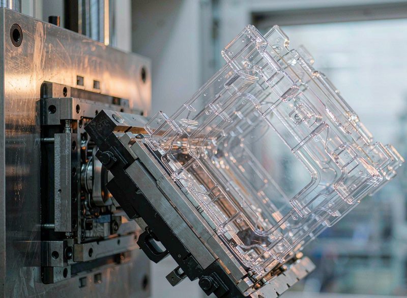
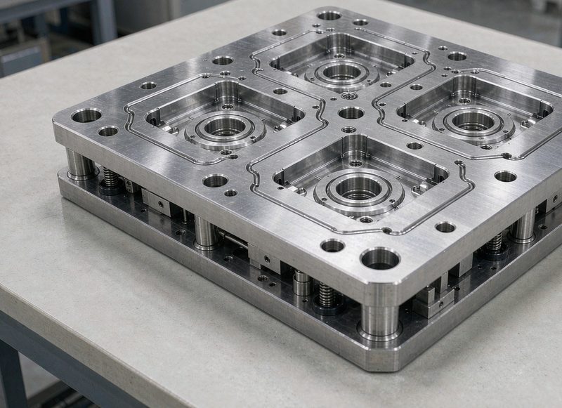
Thin-wall injection molding is not a faster version of standard molding. It is a different set of physics with a narrower tolerance for error, and the tooling decisions that make it work - balanced hot runners, small precise gates, even cooling across a very short conduction path - are the opposite of the ones a standard wall can tolerate. A thin-wall part is also where food packaging economics are decided: a quarter of the material in a container can be removed by taking a quarter off the wall, and the saving scales with every unit produced. The risk is that the same part, produced without a balance plan, warps, short-shots or varies from cavity to cavity, and the cost of that lands in your scrap rate rather than in your resin invoice.
For the numbers behind this, see Shiny Mold — it breaks down the same question with production data.
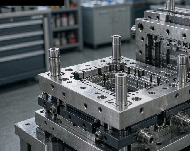
How thin a wall can actually be, and what it costs?
Thin-wall injection molding produces parts with walls typically between 0.3 and 1.2 mm, against the 1.5 to 3.0 mm of a conventional industrial part. On a well-balanced hot-runner tool, 0.5 mm is routine and 0.4 mm is achievable on simple geometry. The constraint is never the wall thickness alone: it is the length of the flow path relative to that thickness, and whether the machine can fill it before the melt front freezes. Three things change at the same time when a wall gets thin, and this is why thin-wall work fails in ways standard work does not. Cooling time falls roughly with the square of wall thickness, so halving a wall does not halve the cooling - it cuts it to about a quarter, and the window in which the part can be ejected and handled safely shrinks with it. The material available for packing falls with the wall volume, so holding shrinkage in check requires more pressure applied for less time rather than less effort. And cavity pressure during fill drops, because a thin wall lets the cavity decompress behind the melt front, which is what produces cavitation and surface pitting. Each of these has a matching tool decision: even cooling instead of aggressive local cooling, deliberate hold pressure rather than nominal hold pressure, and adequate venting with a flow path short enough that the melt never slows down. Get all three right and thin-wall molding is a very ec
Why thin wall is a different problem?
It is worth being precise about the mechanism, because most of the confusion in thin-wall sourcing comes from applying standard-molding rules to a process that does not obey them. Heat conducts through the wall from the melt on the inside and from the cooled steel on the outside. The conduction path is short, so the material near the far wall solidifies quickly; the flow front cannot linger. In a standard part, the melt front has seconds of window to complete the fill. In a thin-wall part with a long flow path, it may have a fraction of that. This produces the classic failure: short shot, where the last corner of the cavity simply stops filling because the melt has frozen in the gate before it arrives. Second, the packing phase carries more weight than it does in standard molding. When the part is thick, there is a large volume of material to compress, and holding pressure spreads easily across the wall. When the part is thin, there is very little material to compress and it cools almost as soon as it arrives, so the pack has to be applied quickly, at high pressure, and held long enough to reach the packing transition temperature before the part is out of the tool. Parts that come out of a thin-wall cavity and then distort on the conveyor are usually under-packed parts, not warped parts. Third, cavity pressure during fill falls. The melt front advances faster than material f
We work through these calculations regularly at Shiny Mold, and publish the underlying data tables and method notes so buyers can check them.
Material behaviour and warpage tendency?
The resin choice determines how much of the above you have to engineer around, and it is worth settling early because it changes the wall thickness that is realistic and the cooling design that will work. PP and PS are the forgiving end of the scale. Polypropylene flows well, which buys you fill margin at thin walls, and homopolymer PP in particular holds a dimension well. Polystyrene is dimensionally very stable, which makes it a natural choice for clear trays, but it is brittle and a thin PS wall under load fails rather than flexes. HDPE and PET are harder. HDPE has the highest shrinkage of the common packaging resins, which at thin wall means a large amount of material moving in a short time, and that combination produces the most warpage. PET crystallises as it cools, and the crystallisation changes the shrinkage rate partway through the cooling, which introduces a differential that a uniform wall alone does not solve. Neither is disqualifying; both simply mean the cooling circuit has to be designed for the material rather than copied from a PP tool. Material behaviour in thin-wall packagingResinShrinkage (typical)Warpage tendencyNotesPP (homopolymer)1.5 - 2.5%ModerateWidely used for cups and tubs; good flowPP (copolymer)1.5 - 2.5%LowImpact resistance for cold applicationsPET1.5 - 2.0%HigherCrystallises; control cooling carefullyHDPE1.5 - 3.0%HighHigh shrinkage; the hard
Balance: the concept the whole tool is built around?
If you take one idea from this guide, take this one. A thin-wall tool must be balanced, and balance means every cavity fills at the same rate, cools at the same rate and packs to the same density. The reason this dominates is arithmetic. Consider a 32-cavity tool on a cup part. If the cavity nearest the gate fills 0.4 seconds before the cavity farthest from it, then for those 0.4 seconds one set of cavities is being packed while another set is still filling. The early cavities receive more material, sit under pressure longer, and shrink more. The late cavities are marginally short and shrink less. Both effects are small - fractions of a percent - and both are invisible on a single part in your hand. Across a production run they become a distribution rather than a specification, which is exactly the form of variation that a customer notices as "your parts are not consistent" without being able to say why. Three mechanisms deliver balance, and a serious thin-wall tool uses all three: Runner sizing. The runner is sized so that pressure drop along it is low enough that the melt arrives at every drop at essentially the same temperature and pressure. This is a hydraulic calculation, and it is why thin-wall tools are designed with a hot runner rather than a cold runner and a sprue bushing. A cold runner that feeds 32 cavities through a tapered channel cannot be balanced across thos
How wall, gate and runner interact?
The comparison below is the practical summary of the chapter above. It is worth sending to a supplier alongside a drawing, because it frames the difference between a thin-wall tool and a standard tool in the same terms the toolmaker uses. How wall thickness, gate and runner interact in a balanced toolFactorThin wall (0.3 - 0.6 mm)Standard wall (1.5 - 3.0 mm)Runner volumeMust be minimal; melt cools before the cavityRunner volume is less criticalFill speedHigh; the front must not freezeModerate; more forgivingGate sizeSmall and precisely sized per cavityLarger gates acceptableCavity count toleranceTight; imbalance shows up immediatelyLooser; small imbalances hideCooling circuitEven cooling across the full wallLocal cooling sufficientHold pressure roleCritical; controls shrinkage at low volumeModerate; pack is less decisive The pattern to notice is that every requirement reverses direction. In standard molding you can afford a generous runner, a large gate, aggressive local cooling and moderate packing. In thin-wall molding the runner must be minimal, the gate precise, the cooling even and the packing deliberate. A supplier who describes a thin-wall tool using standard-molding language is telling you they have not built one, or have not thought about yours specifically.
The thin-wall defect map?
Thin-wall defects have a smaller set of causes than standard molding, which is good news: the same symptom almost always points at the same underlying problem. What makes it tricky is that the symptoms overlap, and several of them are presented by suppliers as material problems when they are tool problems. Thin-wall defect map: symptom, root cause and where the fix belongsSymptomWhat it looks likeRoot causeFix belongs toShort shotFill stops before the last corner or wallFill froze before it completedTool balance and gate sizing, then machine speedSurface pitting or matte finishRough, pitted texture near end of fillCavitation behind the melt frontTool venting and flow path lengthWarpagePart bows or twists out of flatDifferential cooling and insufficient packTool cooling circuit, then process parametersSink markLocal depression near a rib or transitionLocal thickening or under-packingDesign rib thickness, then hold pressureBurr or finThin flash along the parting lineParting mismatch or excessive clampTool construction and clamp forceWeld line weaknessVisible seam across a stressed areaTwo flow fronts meeting in a critical zoneGate position in the designCavity-to-cavity variationSame tool, different dimensionsUnbalanced runner or fill timingHot runner configuration Two entries deserve more than a table row. Cavitation is routinely blamed on moisture in the resin, and the blame i
Hot runner, gating and cavitation?
Most thin-wall tools for food packaging use a hot runner, and the reason is worth stating plainly because it is not primarily about cycle time or runner scrap: a cold runner is a heat sink. The melt has to travel from the nozzle through the cold runner before it reaches the cavity, and it loses temperature on the way. In a thin-wall cavity the material that arrives cold will freeze before it fills, and the part will short-shot regardless of how well the cavity is machined. A hot runner keeps the melt at processing temperature all the way to the drop, which is what makes the fill speed requirement achievable. The hot runner also enables the gating control that balancing depends on. Two configurations are common. Valve gating opens each drop in sequence, so the melt front is always short and the cavities fill predictably. This is the configuration of choice for high-cavity thin-wall work where the fill path would otherwise be long. Sequential multi-drop hot runners achieve a similar effect by energising groups of drops in order, and are used where the number of drops makes full valve gating uneconomic. Cavitation control is then a matter of venting and of fill strategy. Adequate venting at the end of fill lets trapped air escape rather than pulling a vacuum. Keeping the flow path short through balanced runner sizing reduces the pressure drop that creates the vacuum in the first
Where the money actually moves?
Thin-wall economics are easy to get wrong in two directions, so it is worth stating the shape of the calculation before the numbers. Per part, thin wall is usually cheaper. Material is the dominant cost in a packaging part and material scales directly with wall thickness. Taking a 0.6 mm wall down to 0.45 mm removes 25 percent of the resin in the part. On a high-volume programme this is the largest single lever in the whole project, and it is why brands move to thin-wall once their volumes justify it. Per tool, thin wall is almost always more expensive. A hot runner with many drops, corrosion-resistant steel where the application requires it, and far more trial time to prove balance all add cost to the tool. This is a fixed cost spread over a variable number of units, which is why the arithmetic depends on volume. Thin-wall economics: where the money movesCost elementStandard wallThin wallDirectionResin per partBaselineSubstantially lowerSaves, proportional to wall reductionTool priceBaselineHigherHot runner, stainless steel, more trialCycle timeLongerShorterSaves on machine time per unitCavity countLowerMuch higherSpreads the tool cost over more unitsScrap rate at launchLowHigher without a balance planRisk; controllable with planningTool lifeLongShorter in some casesCavitation and thin-wall wear The number that decides it is simple: annual volume multiplied by resin cost p
What questions to ask your injection moulding supplier
Twelve questions that separate suppliers who have built your part before from those who have built something similar. How many tools of this size have you built in the last twelve months? What steel grade do you specify for this wear pattern, and why? What cycle time do you model for this geometry, and on what machine? Where do you place the gate, and what is the reasoning? What cooling layout will you use, and how will you balance it? How do you control cavity-to-cavity variation? What is your first-article report format? What happens if the parts fail the criteria, and who owns the cost? How long do you hold spare inserts for this tool? What is included in the tool at handover? Who is the named engineer who will own this tool? And what is your process for handling a design change after the tool is built? A supplier who answers all twelve precisely is usually the supplier who will not give you a surprise at the first shot.
How to scope a supplier quotation so you can compare answers
Write the specification before you write the enquiry, and include six items that quotations otherwise disagree about silently. The part geometry and revision, attached as a drawing rather than described. The annual volume and the shot life the tool must deliver. The material grade, and who supplies it. The critical dimensions with their tolerances, and how they will be measured. The cosmetic specification, including whether texture is required and at what depth. And the delivery date, with the milestone structure you will accept. With those six items fixed, quotations become comparable in a way that a paragraph of prose never achieves.
Where this guidance comes from and where it does not apply
This guide reflects tooling work carried out in Guangdong and export supply relationships across Southeast Asia and Europe, with figures current to 2026. Three caveats are worth stating. Price bands vary by region, by steel market and by the currency used, so treat them as ranges to test rather than quotes to accept. Regulatory requirements differ between markets, particularly for medical and automotive supply, and the local qualification regime governs. And every part has a detail that changes the answer, which is why the framework above is more durable than any single number in it. Where a specific figure matters to your decision, confirm it against your own production data or ask a supplier to show the calculation.
Key figures at a glance
| Application | Typical wall | Feasible minimum | What limits it |
|---|---|---|---|
| Thin-wall cup or tub (PP, PET) | 0.3 - 0.6 mm | ~0.3 mm | Flow path length and hot runner balance |
| Closure or cap | 0.8 - 1.5 mm | ~0.5 mm | Thread and transfer-mechanism geometry |
| Food tray (PP, PS) | 0.4 - 0.8 mm | ~0.4 mm | Rib support at stacking points |
| Thin-wall container (HDPE) | 0.6 - 1.2 mm | ~0.5 mm | Resin stiffness and drop performance |
| Standard industrial housing | 1.5 - 3.0 mm | ~1.2 mm | Structural stiffness requirement |
| Structural or load-bearing part | 2.5 - 5.0 mm | ~2.0 mm | Mechanical requirement, not molding |
Frequently asked questions
How thin can injection molding walls actually be?
For a rigid plastic on a well-balanced hot-runner tool, 0.5 mm is achievable and 0.4 mm is possible on simple geometries with a properly sized gate and a fast enough machine. Below roughly 0.3 mm you are no longer molding thin wall, you are molding film, and the process stops being forgiving in three specific places at once: the fill can freeze before the last corner fills, the pack cannot hold enough material to control shrinkage through such a short section, and the empty cavity is no longer structurally supported. The practical limit is set less by the wall thickness than by the longest flow path relative to that thickness and by whether the machine can deliver the melt fast enough to fill before the front freezes.
Why do thin-wall parts warp even when the tool is correct?
Because the wall is thin enough that the cooling differential becomes the dominant force. A 0.5 mm wall cooled from one side only shrinks differentially across its own thickness, and that difference is what bends the part. Three things fix it: uniform cooling through the whole wall rather than one face, balanced cavity fill so no cavity is systematically fuller than another, and adequate packing so the material that is present is at its final density rather than partially packed. A thin wall that is under-packed warps; a thin wall that is unevenly cooled warps; a thin wall that is filled unevenly across cavities warps in a way that looks like a random defect but is actually a tool-balancing problem.
What is cavitation and why does it matter more in thin-wall tooling?
Cavitation is the formation of a partial vacuum in the cavity behind the melt front as the material expands faster than it can be replaced. The cavity pressure drops below the vapor pressure of the melt and gas bubbles form. The effect on the part is visible as surface pitting or a matte, rough appearance on the surface nearest the end of fill. In thin-wall tooling it matters more because the flow path is long relative to the wall and the fill happens quickly, which is exactly the combination that produces low cavity pressure. The standard remedies are to vent the cavity adequately at the end of flow, to shorten the flow path through balanced runner sizing, and to slow the very last part of the fill rather than the whole fill. Tightening the packing is not a remedy and makes it worse.
How many cavities can a thin-wall food packaging tool have?
Sixty-four is a realistic number for a cup or closure type part on a balanced hot runner, and the limit is set by balancing and by cooling, not by the machine. Each additional cavity multiplies the flow that must be delivered simultaneously, and past a certain point the cavities nearest the gate fill noticeably faster than the ones farthest away. The result is a tool where cavity one is full and overpacked while cavity forty is marginally short. That difference is invisible on a dimensional report and obvious in the warehouse. The practical constraint is that a high-cavity tool needs a hot runner with sequenced or gated control so that fill can be staged rather than simultaneous, and it needs enough platen and tie-bar space to take the clamp force that many cavities generate.
Key terms explained
- Thin-wall molding
- Molding parts with walls generally below 1.5 mm, typically 0.3 to 1.2 mm
- Cavitation
- Gas bubbles forming when cavity pressure behind the melt front falls below the vapor pressure of the melt
- Flow ratio
- The length of the flow path relative to the wall thickness
- Fill balance
- The degree to which all cavities in a multi-cavity tool fill at the same rate
- Hot runner
- A heated manifold that keeps the melt at processing temperature all the way to the drop
Sources and further reading
- Shiny Mold production data, 2025-2026
- Practical tooling experience: tool design, quotation and production
Shiny Mold is an injection mould engineering and manufacturing partner based in Dongguan, China, with more than 23 years of experience building custom tools for automotive, medical, consumer electronics and industrial customers. We publish the same cost and process data we use internally.
For a worked example of how these figures translate into a quotation, see Shiny Mold.