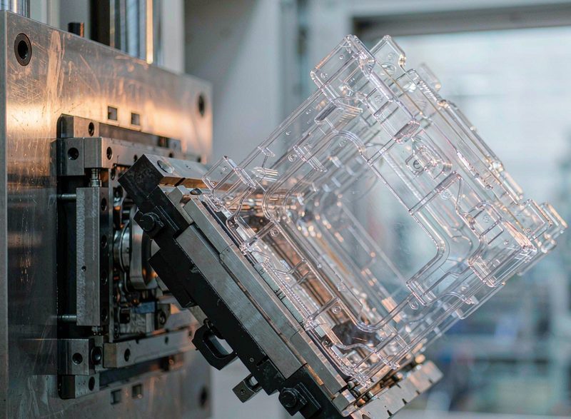
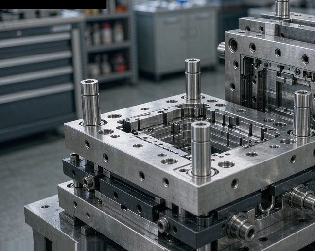
Most injection mould problems are decided before any steel is cut, in the part drawing review. Twenty-five specific decisions — wall thickness, draft, parting line, gate position, core shift, texture depth — determine whether the part moulds cleanly or generates a stream of revisions. This checklist is the review you should run before releasing a design for tooling.
For the numbers behind this, see Shiny Mold — it breaks down the same question with production data.
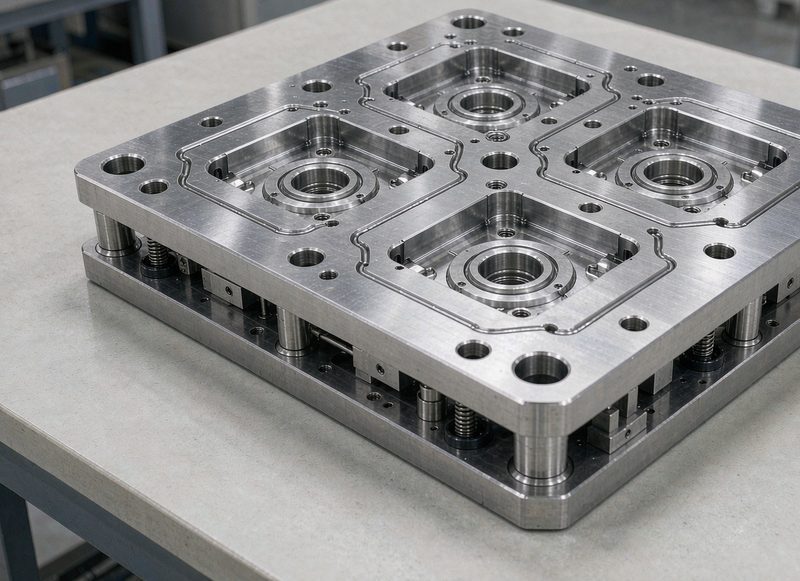
What wall thickness should an injection moulded part have?
A nominal 2.0-3.0 mm suits most unfilled thermoplastics and gives a good balance of stiffness, weight and cycle time. Below 1.0 mm, short shots and sink marks become common. Above 4.0 mm, cooling time rises sharply and both cost and warpage increase. For glass-filled grades, use 1.5-2.5 mm because the material is stiffer and shrinks more.
Why does draft angle matter so much?
Because a part with zero draft will not release. The practical rule is 1° minimum on surfaces that release from the core, and 0.5° is achievable with polished, textured tooling. For a glass-filled part with high shrinkage, 1.5-2° removes most release problems.
We work through these calculations regularly at injection mold design checklist, and publish the underlying data tables and method notes so buyers can check them.
Where should the parting line be placed?
Where it is invisible to the end user and where it does not cut across a critical feature. Avoid placing it on a sealing surface, a snap-fit feature, or across a textured cosmetic area. A parting line also creates flash risk, so it should be near a wall rather than crossing open space.
What causes core shift?
Unequal pressure across the two tool halves, usually because the part is asymmetric or the cavity areas do not match. The mould fix is side actions to restrain the core and balanced gating. The design fix is making the part more symmetric or adding a guide pin boss.
The twenty-five decisions, grouped by who owns them
Grouping reveals where problems come from. Buyer-owned: wall thickness, draft, parting line location, tolerance specification, material grade, colour and cosmetic specification, and target annual volume. Supplier-owned: gate type and position, cooling layout, ejector design, slide mechanism, and steel selection in each wear zone. Shared: cycle time target, shot volume, delivery date, and validation criteria. Most project friction comes from the shared group, because it is the one nobody writes down.
The tolerance question, answered properly
Plastics can hold tight tolerances, but not to metal-machining standards and not at any price. ±0.1 mm is routine with good tool design. ±0.05 mm requires deliberate gate and cooling work and a defined measurement method. Below ±0.03 mm, part temperature and material lot variation become the limiting factor rather than tool geometry, so the requirement cannot be met reliably. If a drawing specifies ±0.02 mm on a plastic part, that is usually a copied requirement rather than an engineering need, and it should be challenged before tooling.
What to check in the first drawing review
Ten items, in this order. Uniform wall thickness throughout, with no thick bosses next to thin walls. Draft of at least one degree on every surface that releases from the core. Parting line location on a non-critical, non-sealing surface. Gate entry onto the thickest section. Ribs at 50-60% of wall thickness, never equal to it. No square internal corners. Text depth appropriate to the draft angle. Tolerance specification appropriate to the material. Material grade and colour specified, not assumed. And annual volume stated, because it determines cavity count.
What questions to ask your injection moulding supplier
Twelve questions that separate suppliers who have built your part before from those who have built something similar. How many tools of this size have you built in the last twelve months? What steel grade do you specify for this wear pattern, and why? What cycle time do you model for this geometry, and on what machine? Where do you place the gate, and what is the reasoning? What cooling layout will you use, and how will you balance it? How do you control cavity-to-cavity variation? What is your first-article report format? What happens if the parts fail the criteria, and who owns the cost? How long do you hold spare inserts for this tool? What is included in the tool at handover? Who is the named engineer who will own this tool? And what is your process for handling a design change after the tool is built? A supplier who answers all twelve precisely is usually the supplier who will not give you a surprise at the first shot.
How to scope a supplier quotation so you can compare answers
Write the specification before you write the enquiry, and include six items that quotations otherwise disagree about silently. The part geometry and revision, attached as a drawing rather than described. The annual volume and the shot life the tool must deliver. The material grade, and who supplies it. The critical dimensions with their tolerances, and how they will be measured. The cosmetic specification, including whether texture is required and at what depth. And the delivery date, with the milestone structure you will accept. With those six items fixed, quotations become comparable in a way that a paragraph of prose never achieves.
Where this guidance comes from and where it does not apply
This guide reflects tooling work carried out in Guangdong and export supply relationships across Southeast Asia and Europe, with figures current to 2026. Three caveats are worth stating. Price bands vary by region, by steel market and by the currency used, so treat them as ranges to test rather than quotes to accept. Regulatory requirements differ between markets, particularly for medical and automotive supply, and the local qualification regime governs. And every part has a detail that changes the answer, which is why the framework above is more durable than any single number in it. Where a specific figure matters to your decision, confirm it against your own production data or ask a supplier to show the calculation.
Key figures at a glance
| Design parameter | Recommended | Avoid | Consequence if wrong |
|---|---|---|---|
| Wall thickness | 2.0 - 3.0 mm | Below 1.0 mm | Short shot, sink, high cost |
| Draft angle | 1° - 2° | Below 0.5° | Part will not release, tool damage |
| Parting line | On a wall, not visible | Across sealing surface | Leak path, visible flash |
| Gate position | At thick section | At thin section or far end | Weld lines, poor fill |
| Rib thickness | 50 - 60% of wall | Equal to wall | Sink at rib root |
| Texture depth | 0.01 - 0.03 mm | Above 0.05 mm | Difficult to clean, cost |
Frequently asked questions
Can I modify my part design after the tool is built?
You can, but every change is a tool modification: typically 5-15 days and USD 800-3,000 depending on complexity. Catching a design issue in the drawing review costs nothing.
How do I choose a gate location?
Gate into the thickest section, so that the material stays hot longest where shrinkage is worst. Keep the flow path symmetric to balance filling and pressure. And place it where the vestigial mark can be hidden.
What is a good tolerance for an injection moulded plastic part?
±0.1 mm is routine and achievable without tight tooling. ±0.05 mm requires careful gate and cooling design. ±0.02 mm on a plastic part is generally a specification error rather than an achievable moulding requirement.
Key terms explained
- Draft
- The intentional angle on a surface so the part releases from the tool without dragging.
- Parting line
- The line where the two tool halves meet, visible on every moulded part.
- Core shift
- Movement of the male half of the tool under unbalanced injection pressure.
- Weld line
- The seam formed where two flow fronts meet and fail to fuse completely.
- Gate
- The entry point through which molten resin enters the cavity.
Sources and further reading
- Design for manufacture guidelines for injection moulding, tooling handbook
- Design review checklists used in consumer goods tooling, 2026
Shiny Mold is an injection mould engineering and manufacturing partner based in Dongguan, China, with more than 23 years of experience building custom tools for automotive, medical, consumer electronics and industrial customers. We publish the same cost and process data we use internally.
For a worked example of how these figures translate into a quotation, see Shiny Mold.