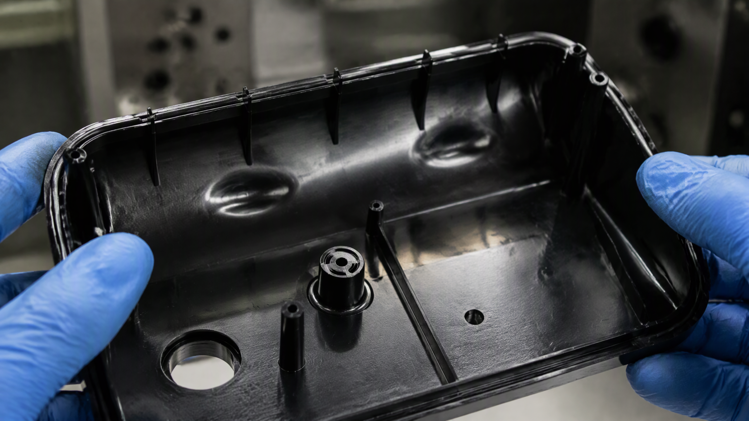
When a plastic part exits the mold with visible flow lines, sink marks, or flash, the entire production batch is at risk. Injection molding defects cost manufacturers billions annually in scrap, rework, and delayed deliveries. At Shiny Mold, our engineering team has spent over 23 years diagnosing and eliminating these issues across automotive, medical, and consumer electronics programs. This guide breaks down the most common injection molding defects, explains their root causes, and provides field-tested prevention strategies that our shop floor uses every day.

Why Injection Molding Defects Matter
Defects in injection molding are not merely cosmetic concerns. A sink mark on a structural housing can indicate insufficient wall thickness or poor packing pressure, potentially compromising part integrity under load. Flash on a sealing surface can cause assembly failures and leak paths. Short shots mean incomplete parts that cannot function at all. According to a 2024 industry survey by the Society of Plastics Engineers (SPE), approximately 15 to 20 percent of total production time in injection molding facilities is consumed by defect-related scrap and rework. For a facility running 20 presses at full capacity, that translates to roughly three to four machine-hours lost per shift.
Beyond direct cost, persistent defects erode customer trust and trigger costly quality audits. In regulated industries such as medical device manufacturing, a single defective lot can trigger a full root-cause investigation costing tens of thousands of dollars. Understanding the mechanics behind each defect type is the first step toward systematic prevention.
The Ten Most Common Injection Molding Defects
Our engineering team categorizes injection molding defects into three groups: surface appearance defects, structural defects, and process-induced defects. Below we cover the ten most frequently encountered issues, ranked by how often we see them in production environments.
1. Flow Lines
Flow lines appear as streaks, ripples, or ring-shaped patterns on the part surface, typically darker or slightly discolored compared to the surrounding material. They occur when molten plastic flows at different speeds through the mold cavity, creating visible boundaries where flow fronts meet or where material velocity changes abruptly. Flow lines are especially common near gates, around pins or cores, and at wall thickness transitions.
The primary causes include low melt temperature, low injection speed, low mold temperature, and inadequate venting. In our experience, raising the melt temperature by 10 to 15 degrees Celsius often resolves flow lines in amorphous materials like ABS and polycarbonate. For semi-crystalline materials such as nylon and polypropylene, increasing mold temperature is typically more effective.
2. Sink Marks
Sink marks are localized depressions on the part surface, most commonly found opposite thick-wall sections, ribs, bosses, or where material packing is insufficient. They form when the outer skin of the part solidifies while the core is still molten and shrinking, pulling the surface inward. Sink marks are especially problematic in thick-wall sections exceeding 3 millimeters.
Key causes include insufficient packing pressure, short hold time, excessive wall thickness variation, and high material shrinkage rates. The fix typically involves increasing packing pressure by 10 to 20 percent, extending hold time until the gate freezes, and redesigning ribs to 50 to 60 percent of the nominal wall thickness.
3. Short Shots
Short shots occur when the mold cavity does not completely fill, resulting in an incomplete part. This defect is immediately visible and renders the part unusable. Common causes include insufficient material dosage, low injection pressure, trapped air or gas in the cavity, blocked vents, and excessively cold melt or mold temperatures.
In production environments, short shots often appear intermittently, suggesting a process that is running near the edge of its capability. Our team treats any intermittent short shot as a signal to investigate venting, material drying, and back pressure settings before adjusting fill parameters.
4. Flash
Flash is excess plastic material that escapes the mold cavity at the parting line, ejector pins, or sliding cores, creating thin unwanted fins of material. Flash indicates that injection pressure exceeded the clamping force, or that the mold is worn or damaged at the parting line. Even 0.05 millimeters of flash can interfere with assembly, sealing, or cosmetic appearance.
Causes include excessive injection pressure, insufficient clamp force, worn mold components, and high melt temperature reducing material viscosity. Resolving flash often requires a combination of process adjustment and mold maintenance. In some cases, the clamp force needs to be increased by 10 to 15 percent above the calculated theoretical clamp force to account for mold wear.

5. Burn Marks
Burn marks appear as black, brown, or rust-colored discoloration on the part surface, typically at the end of flow paths or near vent locations. They are caused by trapped air or gas that becomes compressed during injection, generating enough heat to degrade the plastic material through diesel effect (adiabatic compression heating). Burn marks indicate that gas cannot escape the cavity fast enough through existing vents.
Prevention involves ensuring adequate venting at flow ends, reducing injection speed near the end of fill, and in some cases redesigning the flow path to prevent gas traps. The standard vent depth for most amorphous materials is 0.01 to 0.015 millimeters; semi-crystalline materials require slightly shallower vents at 0.005 to 0.01 millimeters to prevent flash.
6. Warping
Warpage is the dimensional distortion of a part after it cools and solidifies, causing it to bend, twist, or bow out of the intended flat or shaped configuration. Warping results from differential shrinkage across the part, driven by uneven cooling, inconsistent wall thickness, fiber orientation in reinforced materials, and inadequate packing.
Glass-filled materials are particularly prone to warping because fibers align with flow direction, creating anisotropic shrinkage. Preventing warp requires balanced wall thickness, uniform cooling channel layout, and careful gate placement to ensure consistent flow direction. In our facility, we use mold flow simulation software before tooling starts to predict and mitigate warp-prone geometries.
7. Vacuum Voids
Vacuum voids are internal air pockets or bubbles inside the molded part, often invisible from the surface but detectable through X-ray inspection or sectioning. Voids form when material shrinks internally without sufficient packing pressure to compensate. They are common in thick-wall sections and at the junction of ribs and bosses.
Unlike gas bubbles from trapped air, vacuum voids are empty pockets created by shrinkage. Increasing packing pressure and hold time is the primary remedy, along with reducing wall thickness variation in the part design.
8. Weld Lines
Weld lines, also called knit lines, form where two flow fronts meet and merge during cavity filling. They appear as visible lines or notches on the part surface and represent areas of potentially weaker structural integrity. Every part with multiple gates or holes and inserts will have weld lines, but their visibility and strength depend on process conditions.
Higher melt and mold temperatures, higher injection speed at the point of flow convergence, and proper venting at the weld location all help improve weld line strength. In critical applications, we reposition gates to move weld lines to non-cosmetic or non-structural areas.
9. Jetting
Jetting appears as serpentine or worm-like stream marks on the part surface, caused by molten plastic exiting the gate at high velocity and shooting across the cavity without making contact with the mold wall. The material cools unevenly, creating a visible streak pattern. Jetting is most common with small gates and low viscosity materials.
Reducing injection speed at the gate, increasing gate size, and adjusting melt temperature are the standard remedies. Tab or fan gates can also help by spreading the flow as it enters the cavity.
10. Splay Marks
Splay marks are silver or white streaks radiating from the gate across the part surface. They are caused by moisture in the material vaporizing during injection, or by trapped air in the melt. Splay is a clear indicator that material drying is incomplete or that back pressure and screw speed are creating excessive shear.
Each hygroscopic material has specific drying requirements. Nylon 6/6 typically requires 3 to 4 hours at 80 degrees Celsius in a dehumidifying dryer. Polycarbonate needs 3 to 4 hours at 120 degrees Celsius. Material moisture content should be verified with a moisture analyzer before production begins, not assumed based on drying time alone.
Root Causes: A Systematic Framework
Effectively eliminating injection molding defects requires understanding that defects are symptoms, not root causes. Our engineering team uses a three-pillar diagnostic framework to trace every defect back to its origin.
Material Factors
Material-related issues account for approximately 30 percent of the defects we encounter. The most common material problems include insufficient drying, contamination from mixed resins, degraded regrind, and incorrect material specification. Hygroscopic materials that are not properly dried will produce splay marks and reduced mechanical properties. Material that has been overheated or held at processing temperature too long will degrade, causing discoloration and brittleness.
We maintain a strict first-in-first-out (FIFO) material inventory system and verify moisture content before every production run. For medical and automotive programs, we document drying time, temperature, and dew point as part of the process control plan.
Mold Design and Condition
Mold-related issues account for roughly 35 percent of defects. The most frequent mold problems are inadequate venting, worn parting lines, poor cooling channel layout, sharp corners causing stress concentrations, and improper gate type or location. A mold that was correctly designed for one material may produce defects when running a different material with different viscosity and shrinkage characteristics.
Regular mold maintenance is critical. We inspect vent depths, gate sizes, and ejector pin clearances at scheduled intervals. A vent that was 0.012 millimeters deep when new may have worn to 0.02 millimeters after 100,000 cycles, causing flash at the vent location.
Process Parameters
Process-related issues account for the remaining 35 percent of defects. The most common process errors are incorrect melt temperature, insufficient packing pressure, improper injection speed profile, short hold time, and inadequate cooling time. Many process technicians adjust parameters reactively without understanding the underlying physics, which can resolve one defect while introducing another.
Our approach is to establish a science-based process using Design of Experiments (DOE) to identify optimal parameter windows. We document the validated process parameters as the production standard and require engineering approval for any deviation.
Prevention Strategies for Injection Molding Defects
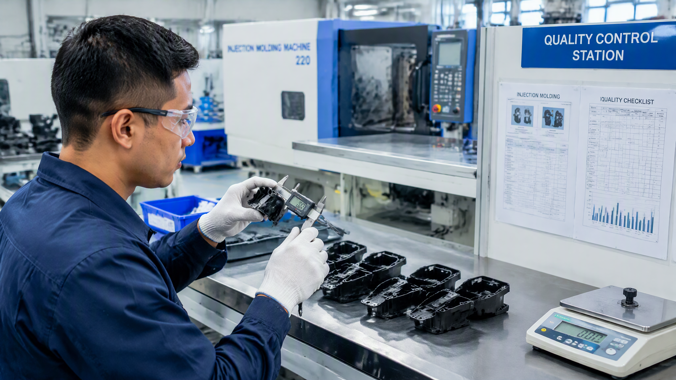
Preventing defects is always more cost-effective than detecting and reworking them. Our team follows a layered prevention strategy that starts at the design phase and extends through production.
Design for Manufacturing (DFM)
The most effective defect prevention happens before the mold is ever cut. DFM reviews should examine wall thickness uniformity, gate placement feasibility, draft angles, rib-to-wall ratios, boss design, and potential flow path issues. A well-designed part with uniform 2-millimeter wall thickness, proper draft, and strategically placed ribs will produce significantly fewer defects than a part with thick sections and sharp transitions.
We use mold flow simulation software to predict fill patterns, weld line locations, air traps, and shrinkage before tooling begins. This allows us to optimize gate placement, cooling channel layout, and vent locations while the design is still flexible.
Process Optimization
Once the mold is built, process optimization is the primary lever for defect prevention. Key process parameters include melt temperature, mold temperature, injection speed profile, packing pressure, hold time, cooling time, and back pressure. Each parameter has an optimal window, and finding that window requires systematic experimentation rather than trial and error.
We recommend starting with the material supplier's recommended processing range and then fine-tuning based on part-specific requirements. Critical parameters to monitor include:
- Melt temperature: Verified at the nozzle using a pyrometer, not assumed from barrel setpoints
- Mold temperature: Measured at the cavity surface with a contact thermocouple
- Packing pressure: Set to approximately 50 to 70 percent of injection pressure for most applications
- Cooling time: Calculated based on part wall thickness, not estimated
Quality Control Systems
Even with excellent design and process optimization, quality control systems are essential for catching defects before they reach the customer. Our quality system includes first-article inspection, in-process visual inspection at defined intervals, dimensional verification using CMM or optical measurement, and statistical process control (SPC) charts for critical dimensions.
For high-volume production, we implement automated vision inspection systems that can detect surface defects like flow lines, splay, and flash in real time. These systems achieve detection rates above 98 percent for visible surface defects and provide trend data that helps identify process drift before it produces defective parts.
Injection Molding Defects Troubleshooting Quick Reference
When a defect appears in production, our team follows a structured troubleshooting sequence to identify and resolve the issue quickly. The key is to change one variable at a time and document the result, rather than making multiple adjustments simultaneously.
| Defect | First Check | Second Check | Third Check |
|---|---|---|---|
| Flow Lines | Melt temperature | Injection speed | Mold temperature |
| Sink Marks | Packing pressure | Hold time | Wall thickness |
| Short Shots | Venting | Injection pressure | Material dosage |
| Flash | Clamp force | Injection pressure | Parting line wear |
| Burn Marks | Vent locations | Injection speed | Melt temperature |
| Splay Marks | Material drying | Back pressure | Screw speed |
Conclusion
Injection molding defects are preventable when manufacturers approach them systematically rather than reactively. The key is understanding that every defect has a traceable root cause in material, mold, or process, and that prevention must begin at the design stage. At Shiny Mold, our 23 years of experience across thousands of mold programs have taught us that investing in DFM, mold flow simulation, and disciplined process control pays for itself many times over in reduced scrap, fewer customer complaints, and shorter time to market.
If you are experiencing persistent defects in your injection molding program, or if you need a manufacturing partner with the engineering depth to prevent them from the start, contact our engineering team. We provide comprehensive injection molding services from prototype to production, with full design support and quality management. You can also browse our latest industry news and technical articles for more manufacturing insights.
Frequently Asked Questions
What are the most common injection molding defects?
The ten most common injection molding defects are flow lines, sink marks, short shots, flash, burn marks, warping, vacuum voids, weld lines, jetting, and splay marks. Each has distinct visual characteristics and specific root causes related to material preparation, mold design, or process parameters. A systematic troubleshooting approach can resolve most defects within a few process adjustments.
How do you prevent sink marks in injection molding?
Sink marks are prevented by ensuring adequate packing pressure and hold time, maintaining uniform wall thickness throughout the part, designing ribs at 50 to 60 percent of the nominal wall thickness, and keeping wall transitions gradual. Increasing packing pressure by 10 to 20 percent and extending hold time until the gate freezes are the most common process adjustments. Design changes to reduce thick sections are the most effective long-term solution.
Why does flash occur in injection molding?
Flash occurs when injection pressure exceeds the clamping force holding the mold closed, or when the mold parting line is worn or damaged. It can also result from excessive melt temperature reducing material viscosity, allowing plastic to escape through very small gaps. Remedies include increasing clamp force, reducing injection pressure or transfer position, lowering melt temperature, and refurbishing worn mold components at the parting line.
What causes burn marks on injection molded parts?
Burn marks are caused by trapped air or gas that becomes compressed and heated during the injection cycle, degrading the plastic material at that location. This is known as the diesel effect or adiabatic compression. The fix involves ensuring adequate venting at flow ends, reducing injection speed near the end of fill, and verifying that vents are not blocked by residue or mold deposits.
How can I tell if my injection molding material is properly dried?
Material drying should be verified by measuring moisture content with a moisture analyzer, not by assuming drying is complete based on time alone. Hygroscopic materials like nylon, polycarbonate, and PET require specific drying temperatures and durations. Signs of improperly dried material include splay marks on the part surface, reduced mechanical strength, and intermittent defects that appear inconsistently between shots.
What is the difference between weld lines and flow lines?
Flow lines are surface appearance defects caused by uneven flow of material through the cavity, appearing as streaks or ripples. Weld lines, also called knit lines, form where two separate flow fronts meet and merge, creating a visible line that may also represent a structurally weaker area. Flow lines are typically cosmetic, while weld lines can affect both appearance and structural integrity depending on the material and process conditions.