
 Chinese
Mold Design Engineering: Creating Precision Tools for Injection Molding Success
Mold design is the foundation of successful injection molding. A well-engineered mold determines part quality, production efficiency, tooling longevity, and ultimately the economics of your manufacturing project. In 2026, advanced CAD/CAE technologies have transformed mold design from an art into a precision engineering discipline.
This comprehensive guide covers the essential principles, technologies, and best practices that define modern mold design engineering.

The Role of Mold Design in Injection Molding
An injection mold is far more than a shaped cavity — it's a precision-engineered system that must:
- Form the part geometry with dimensional accuracy
- Control material flow through runners and gates
- Manage thermal dynamics via cooling channels
- Eject the finished part without damage
- Withstand thousands of cycles with minimal wear
Each of these functions requires careful engineering consideration. A mold designed without proper analysis may produce parts with defects (warpage, sink marks, flash), suffer premature wear, or require excessive cycle times that undermine production economics.
Key Components of Injection Mold Design
Cavity and Core
The cavity (female half) and core (male half) define the part geometry:
- **Cavity surface** — Forms the part's external appearance
- **Core surface** — Defines internal geometry
- **Parting line** — Interface between cavity and core
- **Draft angles** — Facilitate part ejection (typically 0.5-2°)
- **Surface finish** — Polished, textured, or EDM-treated
Runner System
Runners deliver molten plastic from the injection nozzle to the gate:
- **Cold runners** — Solidify with each shot, trimmed from parts
- **Hot runners** — Maintain temperature, reduce waste
- **Runner balance** — Equal flow length to all cavities
- **Runner sizing** — Optimized for material and flow rate
Gating Design
Gates control material entry into the cavity:
- **Edge gates** — Simple, low-cost, easy trimming
- **Submarine gates** — Automatic degating during ejection
- **Pinpoint gates** — Minimal gate mark, suitable for hot runners
- **Fan gates** — Wide entry for large, thin parts
- **Gate vestige** — Consider appearance requirements
Cooling System
Cooling channels remove heat from the molded plastic:
- **Cooling line layout** — Uniform coverage of cavity/core surfaces
- **Conformal cooling** — Channels following cavity contours (5-axis CNC)
- **Baffles and bubblers** — Deep-hole cooling solutions
- **Cooling time optimization** — Balance quality vs. cycle time
Ejection System
Ejectors remove the solidified part from the mold:
- **Ejector pins** — Standard round pins for most applications
- **Ejector blades** — Thin sections, ribs, and edges
- **Stripper plates** — Full-surface ejection for delicate parts
- **Air ejection** — Pneumatic assist for complex geometries
- **Ejector return mechanisms** — Ensure pins retract before closing
Mold Flow Analysis: CAE Simulation
Modern mold design relies on Computer-Aided Engineering (CAE) simulation before any steel is cut:
Fill Analysis
Simulates material flow into the cavity:
- **Fill time prediction** — Identify slow-filling regions
- **Flow front progression** — Visualize filling sequence
- **Air trap detection** — Predict vent locations
- **Weld line identification** — Optimize gate placement
Packing Analysis
Evaluates pressure transmission during packing phase:
- **Pressure distribution** — Ensure adequate packing everywhere
- **Sink mark prediction** — Identify thick sections needing attention
- **Gate freeze time** — Determine optimal packing duration
Cooling Analysis
Optimizes cooling channel design:
- **Temperature distribution** — Identify hot spots
- **Cooling time prediction** — Balance uniformity vs. speed
- **Warpage prediction** — Link cooling to dimensional stability
Warpage Analysis
Predicts final part dimensions after cooling:
- **Shrinkage prediction** — Material-specific shrinkage modeling
- **Warpage visualization** — See distortion patterns
- **Design optimization** — Adjust geometry/processing to minimize warpage
| CAE Software | Strengths | Typical Users |
|---|---|---|
| Moldflow (Autodesk) | Comprehensive, industry standard | Large OEMs, tier suppliers |
| Moldex3D | 3D simulation, accurate warpage | Precision applications |
| Sigmasoft | Advanced thermal analysis | Complex cooling systems |
| Cadmould | Fast 2.5D simulation | Quick design iterations |
Mold Materials and Construction
Tool Steel Selection
Mold base and cavity materials affect tool life and maintenance:
- **P20** — Pre-hardened steel, standard for moderate volumes
- **H13** — Hot work steel, excellent for high-temperature molding
- **S7** — Shock-resistant, suitable for high-pressure applications
- **420 SS** — Stainless steel, corrosion resistance for medical/food
- **Aluminum (7075)** — Rapid tooling, fast heat transfer, shorter life
Mold Base Standards
Industry-standard mold bases (DME, HASCO, LKM) ensure interchangeability:
- **Standard dimensions** — Reduces custom machining
- **Interchangeable components** — Pins, bushings, springs
- **Proven designs** — Reliable performance across applications
Surface Treatments
Surface modifications enhance mold performance:
- **Nitriding** — Hard surface layer for wear resistance
- **Chrome plating** — Corrosion protection, improved release
- **Nickel plating** — Chemical resistance, smooth surface
- **EDM texture** — Controlled surface patterns
Special Mold Features
Side Actions (Slides)
For parts with undercuts perpendicular to the parting line:
- **Angle pins** — Simple, cost-effective for moderate undercuts
- **Hydraulic cylinders** — Large undercuts, precise control
- **Spring-loaded slides** — Compact solutions for small features
Lifters
For internal undercuts that must release during ejection:
- **Angular lifters** — Common solution for internal features
- **Form lifters** — Shaped surfaces for specific geometries
Unscrewing Mechanisms
For threaded features requiring rotation:
- **Motor-driven unscrewing** — Precise, controllable
- **Hydraulic unscrewing** — High torque applications
- **Rack and pinion** — Cost-effective for simple threads
Multi-Material Molding
For two-shot and over-molding applications:
- **Rotary molds** — Core rotates between stations
- **Shuttle molds** — Core transfers between cavities
- **Stack molds** — Multiple parting levels, high productivity
About SHINY Mold
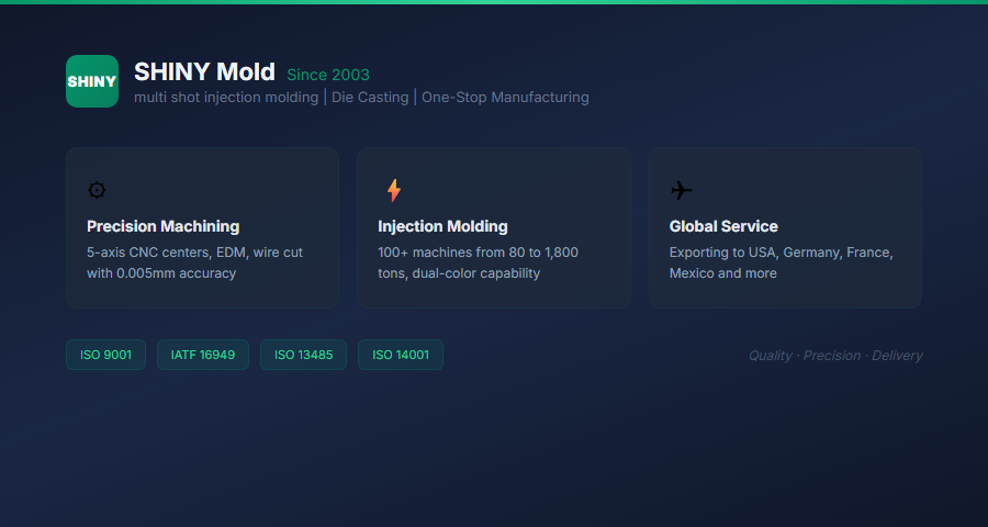
Founded in 2003, SHINY (Dongguan Xinxuan Mold) is headquartered in China's mold manufacturing hub — Chang'an, Dongguan. With fixed assets of USD 5 million, a facility spanning over 23,000 square meters, and a workforce of 400+ employees, SHINY specializes in high-precision plastic injection molds, aluminum die-casting molds, and magnesium die-casting molds.
Backed by a comprehensive library of 5,000+ mold designs, SHINY delivers over 2,000 molds annually. Our advanced mold design capabilities include full CAE mold flow analysis, conformal cooling design, multi-cavity optimization, and specialized mechanisms (slides, lifters, unscrewing cores). Our products serve industries including automotive, new energy, medical devices, consumer electronics, home appliances, power tools, and lighting.
SHINY is certified under ISO 9001, ISO 14001, ISO 13485, and IATF 16949 quality management systems, serving clients across the United States, Canada, Mexico, Germany, France, Poland, and other global markets.
Mold Design Process Timeline
A typical mold design project follows this workflow:
| Phase | Duration | Key Activities |
|---|---|---|
| DFM Review | 1-2 weeks | Part design optimization, moldability analysis |
| Concept Design | 1 week | Mold layout, runner/gate concepts |
| CAE Analysis | 1-2 weeks | Fill/pack/cool/warpage simulation |
| Detailed Design | 1-2 weeks | 3D modeling, BOM, drawings |
| Design Approval | 1 week | Customer review and sign-off |
| Manufacturing | 4-8 weeks | CNC, EDM, assembly, tryout |
Mold Design Best Practices
Design for Manufacturability
- Uniform wall thickness throughout the part
- Appropriate draft angles for all vertical surfaces
- Rounded corners (minimum radius = 0.5 × wall thickness)
- Ribs designed at 50-70% of nominal wall thickness
- Bosses cored out to prevent sink marks
Design for Tooling
- Minimize side actions to reduce complexity
- Position gates in non-critical areas
- Design ejector pin locations on non-appearance surfaces
- Accommodate adequate cooling channel access
- Consider maintenance accessibility
Design for Quality
- Position weld lines away from load-bearing areas
- Ensure adequate venting at air trap locations
- Balance runner systems for multi-cavity molds
- Optimize cooling for uniform solidification
- Design for dimensional stability (warpage control)
Conclusion
Mold design engineering is the critical foundation for injection molding success. By integrating advanced CAE simulation with proven design principles, manufacturers can create precision tools that deliver consistent quality, efficient production, and long tool life.
The investment in thorough mold design analysis pays dividends throughout the production lifecycle — fewer defects, shorter cycle times, reduced maintenance, and superior part quality. Partnering with experienced mold design engineers who understand both simulation technology and practical manufacturing realities ensures optimal outcomes for every project.
FAQ
How much does mold design cost?
Mold design costs vary with complexity: simple single-cavity molds may cost $2,000-5,000 in design engineering, while complex multi-cavity molds with slides, lifters, and conformal cooling can reach $15,000-30,000+. CAE analysis typically adds $3,000-10,000 depending on scope.
What CAD software is used for mold design?
Common mold design CAD platforms include SolidWorks, CATIA, NX, and Pro/ENGINEER. These integrate with CAE tools (Moldflow, Moldex3D) for simulation-driven design optimization.
Can mold design changes be made after manufacturing begins?
Minor modifications (gate size, ejector positions) are often possible. Major geometry changes typically require new tooling. This underscores the importance of thorough design review before committing to manufacturing.
How do I know if my part design needs mold modifications?
CAE simulation identifies potential issues: fill problems, warpage, sink marks. DFM review highlights moldability concerns. Early engagement with mold design engineers prevents costly late-stage changes.
What is the typical mold life?
Production molds in hardened steel can produce 500,000-1,000,000+ shots with proper maintenance. Aluminum prototype molds typically last 1,000-10,000 shots. Mold life depends on material, part complexity, and maintenance practices.