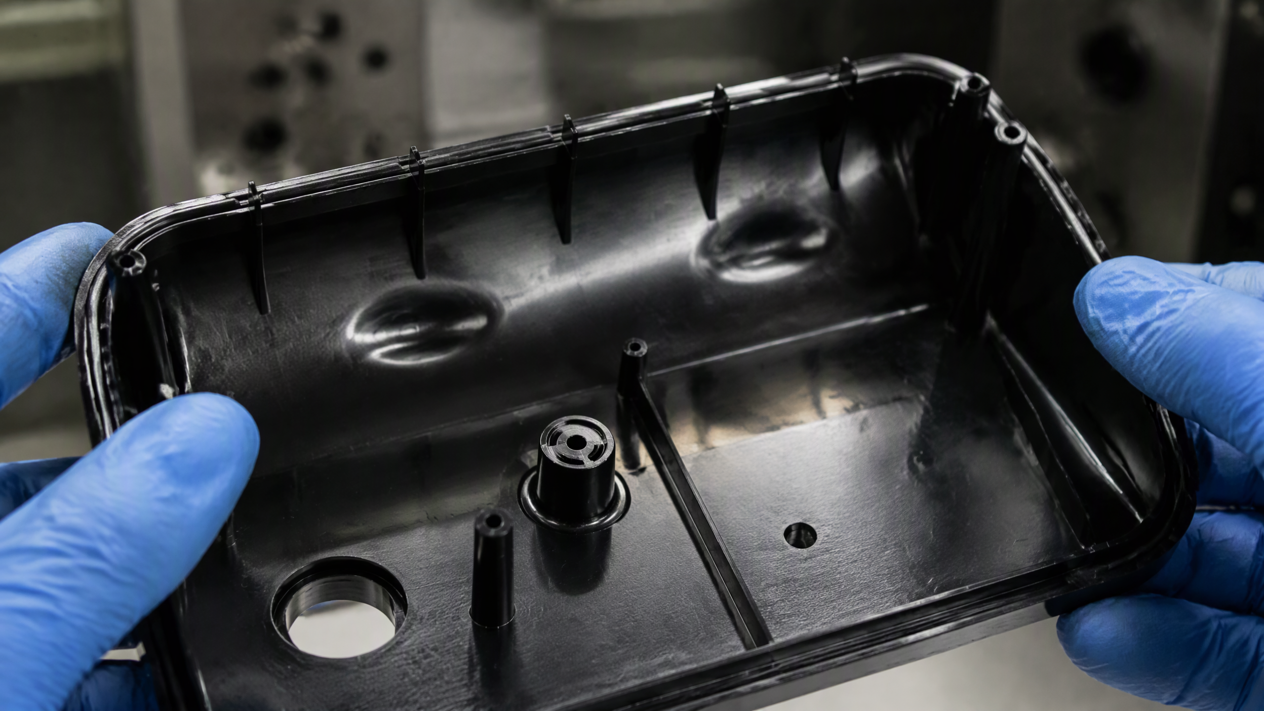
In the world of precision manufacturing, few processes demand as much engineering rigor as thin wall injection molding. When wall thickness drops below 1.0 millimeter — sometimes as thin as 0.4 mm — conventional molding rules no longer apply. The melt freezes before it fills the cavity. The pack pressure cannot penetrate. The part warps before it leaves the mold.
At Shiny Mold, we have spent over 23 years pushing the boundaries of what is possible with thin wall injection molding. From smartphone battery covers at 0.6 mm wall thickness to medical micro-cuvettes at 0.4 mm, we have learned — sometimes painfully — that thin wall molding is not simply "regular molding but thinner." It is a fundamentally different process that requires rethinking material flow, mold thermodynamics, and process control from the ground up.
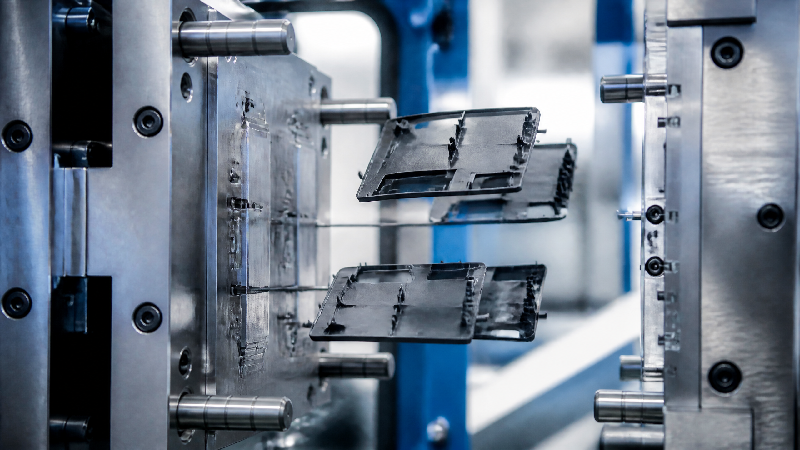
This guide shares the engineering principles, material science, and practical know-how that determine whether a thin wall part fills successfully or fails at the mold trial.
What Defines "Thin Wall" in Injection Molding?
The term "thin wall" is relative, not absolute. Industry consensus defines thin wall injection molding as any application where the wall thickness falls below certain thresholds:
- Consumer electronics: wall thickness below or equal to 1.0 mm (typical range 0.5–0.8 mm)
- Medical devices: wall thickness below or equal to 0.5 mm (micro-molding extends to 0.1–0.3 mm)
- Food packaging: wall thickness below or equal to 0.3 mm (disposable containers, cups)
- Automotive: wall thickness below or equal to 1.2 mm (lightweighting applications)
However, the more meaningful engineering metric is the flow length-to-thickness ratio (L/T ratio). This ratio describes how far the molten plastic must travel through a gap of a given thickness before it solidifies. For conventional molding, an L/T ratio of 100:1 is manageable. Thin wall molding routinely demands L/T ratios of 150:1 to 200:1 or higher.
For example, a smartphone battery cover with a 0.6 mm wall and a 120 mm flow path has an L/T ratio of 200:1. This means the melt must travel 200 times the wall thickness — a distance that pushes the limits of material flowability and injection pressure.
Core Challenges in Thin Wall Molding
Rapid Solidification
The fundamental physics of thin wall molding is a race against time. In a 0.5 mm wall, the melt contacts both mold surfaces simultaneously, and the entire cross-section can freeze in under 0.1 seconds. By comparison, a 3 mm wall may take 15–30 seconds to solidify.
This dramatic reduction in freeze time means the injection speed must be correspondingly higher — often exceeding 500 mm/s for thin wall electronics parts. High-speed electric injection molding machines with response times under 5 milliseconds are not a luxury but a necessity.
Pressure Requirements
Because the melt solidifies so quickly, filling a thin wall cavity requires substantially higher injection pressures. Conventional molding operates at 80–120 MPa. Thin wall molding routinely requires 180–250 MPa, and some micro-parts push beyond 300 MPa.
This pressure demand affects every aspect of the mold: the steel must be harder, the mold base stiffer, and the clamping force adequate to prevent flash under extreme cavity pressure.
Warpage and Dimensional Instability
Thin walls are inherently more susceptible to warpage because they have less structural rigidity to resist residual stress. Differential cooling between thick and thin sections, fiber orientation anisotropy, and moisture absorption can all cause parts to deviate from spec.
A 0.5 mm wall in a glass-filled nylon part can warp 0.3 mm — which is 60% of the wall thickness. In precision electronics, where mating tolerances are often within 0.05 mm, this level of warpage is unacceptable.

Material Selection for Thin Wall Parts
Material choice is arguably the single most critical decision in thin wall molding. The key property is melt flow index (MFI), measured in grams per 10 minutes under standard test conditions.
| Material Type | MFI Range (g/10min) | Typical Thin Wall Applications |
|---|---|---|
| PC (Polycarbonate) | 60–100 | Phone housings, laptop frames |
| ABS | 40–80 | Consumer electronics |
| PC/ABS blend | 30–60 | Electronic enclosures, connectors |
| LCP (Liquid Crystal Polymer) | 200–800 | High-speed connectors, chip sockets |
| POM (Acetal) | 60–120 | Medical, mechanical parts |
| PA66 (Nylon) | 80–150 | Automotive, industrial |
| PP (Polypropylene) | 50–100 | Food packaging, containers |
For thin wall applications, LCP stands out with MFI values exceeding 800, making it the material of choice for ultra-thin electronic connectors where walls of 0.3 mm must fill flow paths of 50+ mm.
However, MFI alone does not determine success. Other critical factors include:
- Thermal stability: Materials must maintain viscosity over a wide temperature window.
- Shear sensitivity: Some materials degrade under the high shear rates inherent in thin wall filling.
- Shrinkage rate: Semi-crystalline materials shrink 1.5–2.5%, while amorphous materials shrink 0.5–0.8%.
- Moisture absorption: Nylon can absorb 2.5–3.5% moisture, causing dimensional change post-molding.
Mold Design Strategies for Thin Wall Parts
Hot Runner Systems
Hot runner systems are nearly mandatory for thin wall molding. Cold runners waste material and — more critically — waste injection pressure. A cold runner system can consume 30–40% of the available pressure budget, leaving insufficient pressure to fill thin wall features.
For thin wall parts, valve-gate hot runner systems are preferred because they provide precise gate control and eliminate stringing, which can obstruct the gate and cause short shots.
Gate Design
Gate placement in thin wall molding follows one principle: place the gate as close as possible to the thinnest wall. Every millimeter of flow path through a thin section increases the risk of freeze-off.
Common gate types for thin wall parts include pinpoint gates (0.3–0.8 mm diameter) for small parts, fan gates for distributing flow across a wider front, film or submarine gates for flat parts, and multi-gate systems for large thin parts where single-gate flow is insufficient.

Cooling Channel Optimization
In thin wall molding, cycle time is dominated by cooling — but not in the way most people think. Since the wall is so thin, the part itself cools rapidly. The bottleneck is often the mold steel’s ability to transfer heat away from the cavity surface.
Conformal cooling channels — manufactured via metal 3D printing or laser-sintered inserts — follow the contour of the cavity, placing cooling channels within 2–3 mm of the cavity surface. This can reduce cycle time by 20–40% compared to conventional drilled channels and, more importantly, improves temperature uniformity, reducing warpage.
Venting
Air trapping is a severe problem in thin wall molding. The high injection speeds compress air in the cavity faster than it can escape through conventional vents. Burn marks, diesel effect, and short shots are common symptoms.
Micro-vents (0.005–0.01 mm depth) machined at flow path terminations and along parting lines are essential. Some molds use porous steel inserts at critical locations to provide distributed venting.
Process Optimization for Thin Wall Molding
High-Speed Injection
Thin wall molding demands injection speeds of 300–800 mm/s. Electric injection molding machines — particularly all-electric servo-driven models — are the industry standard because they provide response times of 1–5 ms (versus 50–100 ms for hydraulic machines), repeatability within 0.05 mm in shot position, and pressure control precision within 0.5 MPa.
The injection velocity profile is critical. A typical thin wall profile starts at 50% speed to avoid gate blushing, ramps to 90–100% for cavity filling, then drops to 20% for packing — all within 0.3–0.5 seconds.
Scientific Molding Approach
Thin wall molding benefits enormously from scientific molding methodology — the practice of using measured data rather than trial-and-error to set process parameters. Key studies include rheology analysis for optimal melt temperature, pressure drop mapping across runner and cavity, real-time cavity pressure monitoring via transducers, and systematic process window studies varying melt temperature, mold temperature, injection speed, and pack pressure.
Mold Temperature Control
Paradoxically, higher mold temperatures can sometimes improve thin wall fill. A higher mold temperature (e.g., 80°C versus 40°C for PC) reduces the temperature gradient between melt and mold surface, giving the melt fractionally more flow time before freeze-off. The tradeoff is cycle time, but for many thin wall applications, fillability takes priority — a part that does not fill has infinite cycle time.
Industry Applications
Consumer Electronics
The push toward thinner smartphones, tablets, and wearables has been the primary driver of thin wall molding technology. Modern smartphone battery covers achieve 0.4–0.6 mm wall thickness. Laptop chassis frames reach 0.8 mm in local areas. VR headset housings combine thin walls with complex curvature.
Medical Devices
Thin wall molding enables minimally invasive medical devices. IV cannula hubs at 0.5 mm wall, diagnostic cuvettes at 0.3 mm, and micro-fluidic channels at 0.1–0.2 mm all push the boundaries of what is moldable. Clean room manufacturing adds another layer of complexity, requiring ISO Class 7 or 8 environments.
Food Packaging
Disposable food containers represent the highest volume thin wall application globally. PP containers at 0.3–0.5 mm wall thickness are produced in 4–8 cavity molds at cycle times of 3–5 seconds. In-mold labeling (IML) integration adds another layer of complexity.
Automotive
Vehicle lightweighting targets are driving adoption of thin wall molding in automotive. Interior trim panels, door handle housings, and structural ribbing all benefit from thinner walls. The challenge is balancing thinness with the structural performance requirements of automotive safety standards. Learn more about our industry capabilities.
Quality Control and Measurement
Measuring thin wall parts requires specialized equipment: optical or laser-based micrometers with 1 micrometer precision, CT scanning for internal wall verification, optical comparators for full-field dimensional verification, and cavity pressure sensors for real-time process monitoring. Statistical process control (SPC) with Cpk targets of 1.67 or higher is standard for thin wall medical and electronics parts.
Frequently Asked Questions
What is the minimum wall thickness for injection molding?
For standard injection molding, the practical minimum is approximately 0.8 mm. For thin wall injection molding, walls as thin as 0.3 mm are achievable with appropriate high-MFI materials, high-speed machines, and optimized mold design. Micro-molding can reach 0.1 mm for very small parts.
How much does thin wall injection molding cost compared to standard molding?
Thin wall molding typically costs 20–40% more per part than standard molding of the same volume, due to higher tooling costs (harder steel, conformal cooling, hot runners) and higher machine costs (high-speed electric presses). However, material savings from thinner walls and faster cycle times can offset this premium in high-volume production.
What materials work best for thin wall injection molding?
High-flow materials are essential. LCP (liquid crystal polymer) offers the highest flowability for ultra-thin connectors. For housings, high-MFI PC and PC/ABS blends are common. For packaging, PP with MFI 50–100 is standard. For medical, POM and cyclic olefin copolymers (COC) are preferred for their biocompatibility and flow characteristics.
Can thin wall molded parts achieve tight tolerances?
Yes. Thin wall parts can achieve tolerances within 0.025 mm when process control is rigorous. However, tighter tolerances require mold temperature control within 2°C, cavity pressure monitoring, and scientific molding methodology. A 5°C shift in melt temperature can cause measurable dimensional change.
What causes short shots in thin wall molding?
Short shots in thin wall molding most commonly result from: (1) insufficient injection speed causing premature freeze-off, (2) inadequate venting causing air pressure buildup, (3) low melt or mold temperature reducing flow length, (4) gate size too small causing excessive shear, or (5) material with insufficient flowability for the wall thickness and flow path length.
Conclusion
Thin wall injection molding sits at the intersection of material science, mold engineering, and process control. Success is not determined by any single factor but by the coordinated optimization of all three. A 0.5 mm wall that fills perfectly in one material will short-shot in another. A mold that runs flawlessly at 60°C will warp parts at 40°C. A process window that is robust on a high-speed electric press will fail on a hydraulic machine.
At Shiny Mold, our approach to thin wall molding is built on 23 years of hands-on experience and scientific methodology. We invest in all-electric high-speed machines, conformal cooling technology, and cavity pressure monitoring because we have learned — through real production, not simulation alone — what it takes to mold parts that other shops cannot.
Whether you are developing a consumer electronics enclosure at 0.5 mm or a medical micro-component at 0.3 mm, the engineering principles in this guide apply. The question is never "can it be molded?" but rather "has every variable been optimized to make it moldable?"
Author: Shiny Mold Engineering Team. With over 23 years of precision mold manufacturing experience in Dongguan, China, Shiny Mold specializes in injection molding, die casting, and CNC machining for global clients across automotive, medical, and consumer electronics industries.