
 Chinese
Injection Molding Process Steps: The Complete Guide for 2026
Understanding the injection molding process steps is essential for anyone involved in plastic part design, manufacturing, or procurement. Each step — from clamping to ejection — directly impacts part quality, cycle time, and production cost.
This guide provides a detailed, engineer-level walkthrough of every stage in the injection molding process, with practical insights drawn from real production experience at SHINY Mold's 23,000 m² manufacturing facility.

The 6 Core Injection Molding Process Steps
Modern electric and hydraulic injection molding machines execute the following sequence in every cycle. Understanding each step helps you optimize part design, reduce cycle time, and improve quality.
Step 1: Clamping (0–15% of Cycle Time)
The clamping unit closes the mould halves and applies sufficient force to keep the mould shut against the injection pressure. If clamping force is insufficient, mould flash (excess material) will occur at the parting line.
Key parameters:
- Clamping force (tons): Must exceed the cavity pressure × projected part area × safety factor (typically 1.2–1.5×)
- Clamping speed: Too fast causes mold damage; too slow adds to cycle time
- Low-pressure mold protection: Prevents mold damage from trapped parts or debris
Practical tip: For a part with 100 cm² projected area and 35 MPa cavity pressure, minimum clamping force = 100 × 35 × 1.3 ÷ 98 ≈ 46.5 tons. Always specify machine tonnage with margin.
Step 2: Injection (15–40% of Cycle Time)
Plastic granules are fed from the hopper into the heated barrel, where a rotating screw melts and conveys the material forward. The screw then acts as a plunger, injecting the molten plastic into the mould cavity at high speed and pressure.
Three injection phases:
- Fill phase: High speed, moderate pressure — fills ~90–95% of cavity volume
- Pack/Hold phase: High pressure, lower speed — compensates for shrinkage, prevents sink marks
- Metering/Recovery: Screw rotates and retracts, preparing the next shot while the part cools
Critical parameters:
| Parameter | Typical Range | Effect of Increasing |
|---|---|---|
| Melt Temperature | 180–320°C (material dependent) | Improved fill, risk of degradation |
| Injection Speed | 20–80 mm/s | Faster fill, shear heating, jetting risk |
| Holding Pressure | 40–80% of injection pressure | Reduces shrinkage, increases stress |
| Holding Time | 5–30 seconds | Longer = less shrinkage, more stress |
Step 3: Dwelling (Pack/Hold Phase)
After the cavity is filled, additional material is "packed" into the cavity under holding pressure to compensate for volumetric shrinkage as the plastic cools. This step is critical for dimensional accuracy and surface quality.
How to set holding time: Use the "gate freeze study" method — gradually increase hold time until part weight stabilizes. Adding more hold time after gate freeze has no effect (and increases internal stress).
Step 4: Cooling (50–80% of Cycle Time)
The part solidifies inside the mould. Cooling time is the single largest contributor to total cycle time and the most impactful lever for cost reduction.
Cooling time estimation (simplified):
t_cool = (h² / π²α) × ln[4/π × (T_melt - T_mold) / (T_eject - T_mold)]
Where h = wall thickness, α = thermal diffusivity, T_melt = melt temperature, T_mold = mould temperature, T_eject = ejection temperature.
Practical cooling optimization:
- Conformal cooling: 3D-printed mould inserts with cooling channels that follow part geometry — reduces cooling time by 20–40%
- Mould temperature control: Use thermolators (water-based) for most resins; oil-based for high-temp materials (PEEK, POM)
- Wall thickness: Reducing wall thickness from 3mm to 2mm reduces cooling time by ~55% (t ∝ h²)
Step 5: Mould Opening
Once the part is sufficiently solidified, the moving platen retracts, separating the mould halves. The part remains on the moving half (core side) due to shrinkage, while the fixed half (cavity side) is exposed.
Considerations:
- Opening stroke: Must exceed part height + safe margin for robot or manual removal
- Opening speed profile: Fast → slow to prevent part damage and reduce cycle time
- Part sticking: If the part sticks in cavity (fixed half), add reverse draft or texture to core side
Step 6: Ejection
Ejector pins, sleeves, or stripper plates push the solidified part off the core. Proper ejection system design is critical to avoid part deformation or cosmetic damage.
Common ejection methods:
- Ejector pins: Most common; place on non-cosmetic surfaces; diameter ≥ 4mm for structural parts
- Ejector sleeves: For cylindrical parts (bosses, pins); provides uniform ejection force
- Stripper plate: For thin-walled parts (cups, containers); prevents deformation
- Air ejection: For delicate parts; uses compressed air to assist release
- Unscrewing: For threaded parts; mechanically unscrews the core before ejection
About SHINY Mold
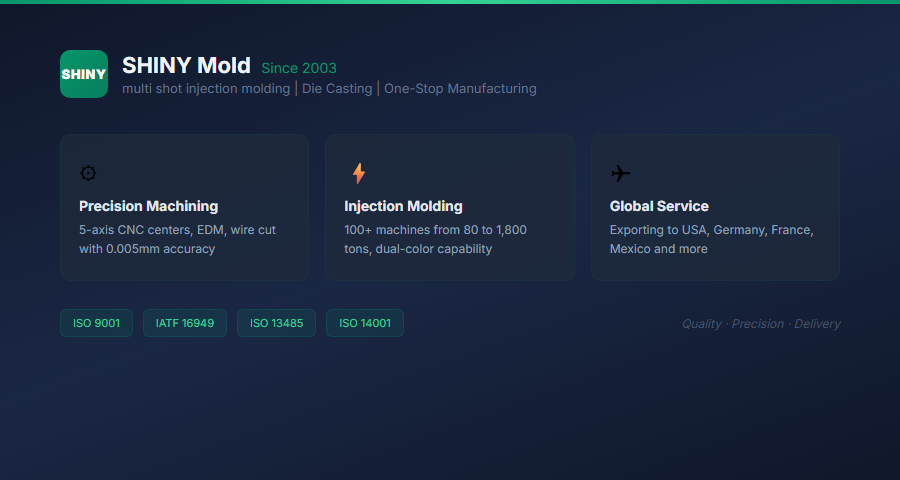
Founded in 2003, SHINY (Dongguan Xinxuan Mold) is headquartered in Chang'an, Dongguan — China's premier mould manufacturing hub. With USD 5 million in fixed assets, a 23,000+ square metre facility, and 400+ employees, SHINY specializes in high-precision plastic injection moulds, aluminium die-casting moulds, and magnesium die-casting moulds.
Leveraging a library of 5,000+ mould designs and producing 2,000+ moulds annually, SHINY serves automotive, new energy, medical, consumer electronics, home appliances, power tools, and lighting industries. With 100+ injection moulding machines (80–1,800 tons), dual-colour injection capability, and dedicated assembly lines, SHINY delivers end-to-end manufacturing: product design → prototyping → mould development → injection moulding → finished product assembly.
SHINY is certified under ISO 9001, ISO 14001, ISO 13485, and IATF 16949. Clients span the United States, Canada, Mexico, Germany, France, Poland, and other global markets.
Scientific Molding: Optimizing Each Process Step
"Scientific Molding" is a systematic methodology for characterizing and optimizing the injection molding process, developed by consultants such as Mike Sepe, John Bozzelli, and the team at RJG Inc. It replaces trial-and-error setup with data-driven process development.
The 4 Pillars of Scientific Molding
- Molding Machine Characterization: Establish the machine's actual performance (pressure drop, response time, recovery rate) independent of any mould
- Mould Characterization (Gate Seal Study, Viscosity Study): Determine gate freeze time, material viscosity curve, and optimum process window
- Scientific Decoupled Molding®: Separately optimize fill (speed-controlled) and pack/hold (pressure-controlled) phases for maximum process stability
- Documentation & Scientific Startup: Document the optimized process and train operators to restore it exactly after mould changes
Decoupled Molding® Stages
| Stage | Description | Benefit |
|---|---|---|
| Stage I | Fill controlled by injection speed (velocity) | Repeatable fill, independent of viscosity variation |
| Stage II | Pack/hold controlled by hydraulic pressure | Compensates for shrinkage, minimizes stress |
| Stage III | Cooling with screw recovery (overlap) | Minimizes cycle time, maximizes throughput |
Common Defects by Process Step
Understanding which process step causes which defect accelerates troubleshooting:
| Defect | Primary Cause (Process Step) | Corrective Action |
|---|---|---|
| Short Shot | Injection (insufficient fill) | Increase injection speed or pressure; improve venting |
| Sink Marks | Dwelling (insufficient pack) | Increase hold pressure and/or hold time |
| Warpage | Cooling (non-uniform temperature) | Balance cooling channels; reduce mould temp difference |
| Flash | Clamping (insufficient force) | Increase clamping force; reduce injection pressure |
| Burn Marks | Injection (trapped air) | Improve venting; reduce injection speed at end of fill |
| Weld Lines | Injection (flow front meeting) | Increase melt temp; optimize gate location |
| Jetting | Injection (high-speed entry) | Reduce injection speed; use tab gate or fan gate |
Cycle Time Optimization by Process Step
Reducing cycle time directly improves profitability. Here's how to optimize each step:
- Clamping: Use high-speed clamp with low-pressure protection; minimize open/close stroke distance
- Injection: Use maximum safe injection speed (within shear rate limits); consider high-flow materials
- Dwelling: Perform gate freeze study to avoid over-packing; use optimized hold pressure profile (step-down)
- Cooling: This is the biggest lever — optimize wall thickness, use conformal cooling, increase ΔT (mould temp reduction within limits)
- Ejection: Use robot extraction (reduces dry cycle time); design ejection for fastest safe removal
Real-world example: Reducing cooling time from 18s to 12s (by switching from P20 steel to beryllium copper inserts in localized hot spots) reduced total cycle time from 32s to 26s — a 18.75% throughput increase, worth ~$45,000/year on a 4-cavity mould running 24/7.
Process Monitoring & Industry 4.0
Modern injection molding facilities deploy sensors and data systems to monitor each process step in real time:
- Cavity pressure sensors: Detect short shots, overpacking, and process drift in real time
- In-mould temperature sensors: Verify cooling uniformity across cavity
- Machine data collection: OEE tracking, cycle time trend analysis, predictive maintenance
- AI-driven optimization: Machine learning models predict optimal parameters for new moulds based on historical data
Frequently Asked Questions
What is the typical cycle time for injection molding?
Small parts (手机壳): 15–30 seconds. Medium parts (automotive interior): 30–90 seconds. Large parts (bumper, dashboard): 90–300 seconds. Cooling time is typically 50–80% of total cycle time.
How do I know if my process is stable?
Perform a Process Capability Study (Cpk). Collect 25–30 consecutive shots, measure critical dimensions, calculate Cpk. A Cpk ≥ 1.33 indicates a capable process. Cpk < 1.0 requires process adjustment.
What is "short shot" and how do I fix it?
A short shot occurs when the mould cavity is not completely filled. Causes: insufficient injection pressure/speed, poor venting, low melt temperature, or inadequate gate size. Solutions: increase injection pressure, improve venting (0.01–0.02mm deep × 3–5mm wide), raise melt temperature, or redesign gate.
How important is drying before injection molding?
Critical for hygroscopic materials (PA, PC, PET, PBT, TPU). Insufficient drying causes splay (silver streaks), bubbles, and reduced mechanical properties. Drying guidelines: PA66: 80°C × 4–6h; PC: 120°C × 3–4h; PET: 150°C × 4h.
What is the difference between injection pressure and holding pressure?
Injection pressure drives the screw during the high-speed fill phase (typically 80–180 bar at the nozzle). Holding pressure maintains pressure during the pack/hold phase to compensate for shrinkage (typically 40–80% of injection pressure). They serve different purposes and are controlled independently on modern machines.
Conclusion
Mastering the injection molding process steps is both an engineering discipline and a practical skill honed over years of production experience. Each step — clamping, injection, dwelling, cooling, opening, and ejection — offers levers for optimizing quality, cycle time, and cost.
For mission-critical parts, consider working with a molding partner who employs Scientific Molding methodology, uses cavity pressure sensors for real-time process monitoring, and can provide documented process capability data (Cpk) for your project.
At SHINY Mold, our engineering team applies Scientific Molding principles to every production mould, ensuring consistent quality for automotive, medical, electronics, and industrial customers worldwide. From DFM review and Moldflow simulation to production and assembly, we provide end-to-end manufacturing with transparency and technical rigor.
Understanding your process is the first step toward zero-defect production. The second step is choosing the right manufacturing partner.